Welcome you visiting my ebay store.If you want to buy more than 10pcs one time,please send e-mail to me.I will give you better price.
The freight is for reference only.Contact the me and choose a shipping method to your location.
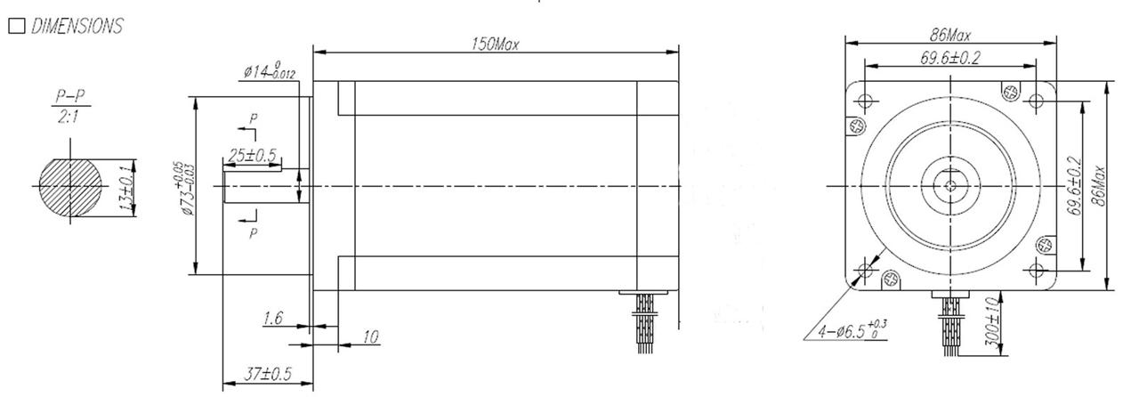
1PCS Nema34HS5435C-37B2 stepper motor 1600oz.in=10.5N.m 3.5A 151mm ,single shaft
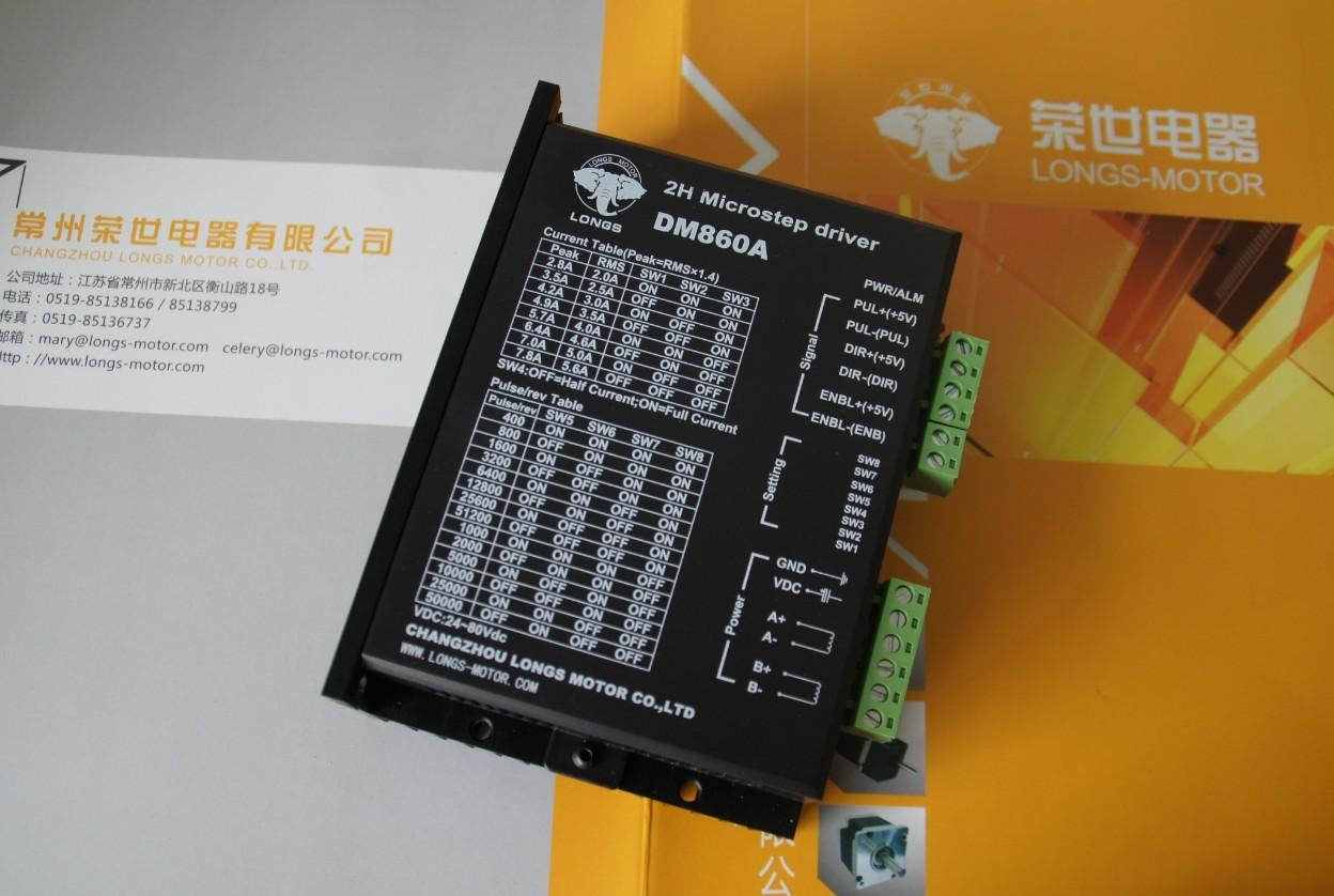
1PCS Stepper motor driver High Perfermance Stepper Driver DM860A Up to7.8A, 24-80VDC
2 pcs Nema 23 stepper motor 425 oz.in
2 pcs Stepper motor driver DM542A ,PEAK current 4.2A, replacing M542
1 pc Power supply 350W-36V( power for Nema 23 motors)
1 pc Power supply 350W-60V( power for Nema 34 motor)
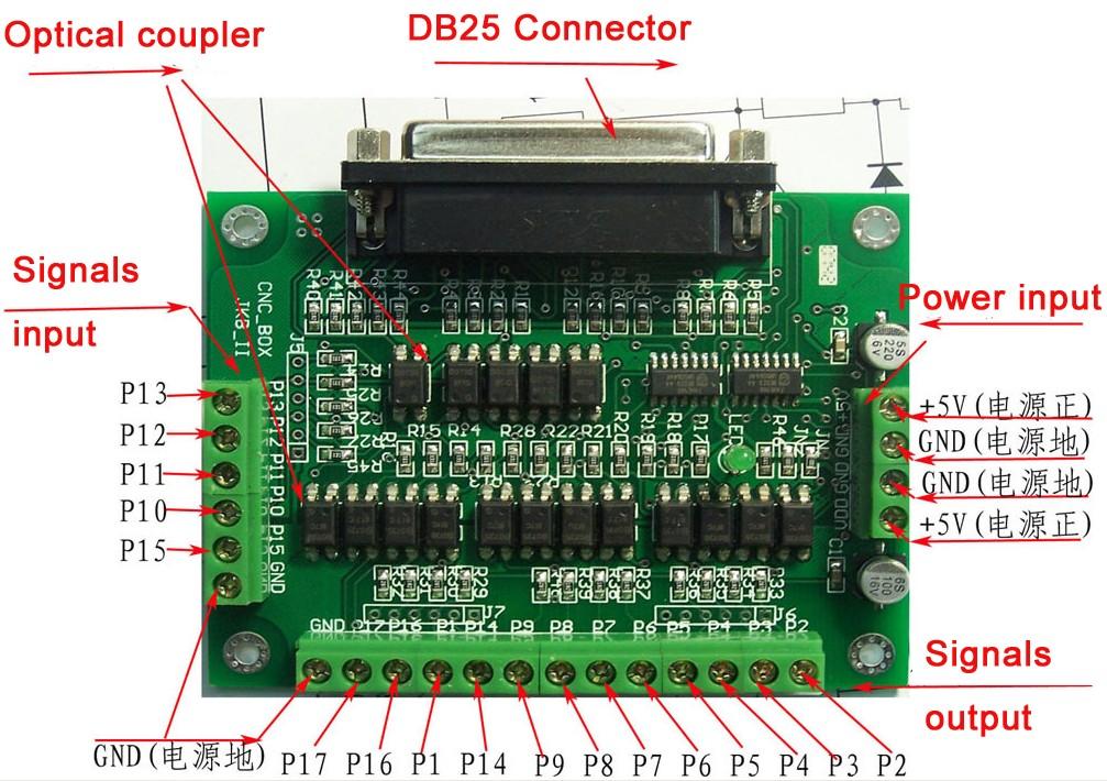
1 pc Breakout board( free offering when you bought all these above)
Detailed information:
1.Nema34 and nema23 stepper motor
|
Model |
Step angel ( ° ) |
Motor Length L(mm) |
Rate Voltage (V) |
Rate Current (A) |
Phase Resistance ( Ω) |
Phase Inductance (mH) |
Holding Torque (oz.in) |
Lead Wire (NO.) |
Rotor Inertia (kg. cm2) |
Motor Weight (kg) |
|
34HS5435C-37B2
|
1.8 |
151 |
5.7 |
3.5 |
1.9 |
22 |
1600 |
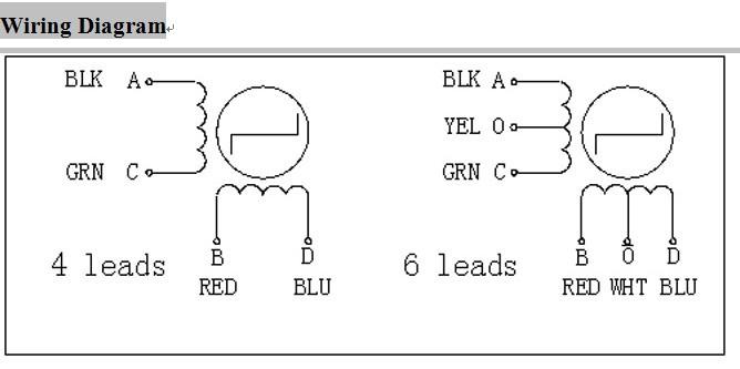
4 |
3.6 |
5
|

Nema 23 stepper motor
|
Model |
Step angel ( ° ) |
Motor Length L(mm) |
Rate Voltage (V) |
Rate Current (A) |
Phase Resistance ( Ω ) |
Phase Inductance (mH) |
Holding Torque (oz.in) |
Lead Wire (NO.) |
Rotor Inertia (kg. c?) |
Motor Weight (kg) |
|
23HS9430 |
1.8 |
115 |
6.4 |
3 |
2.1 |
9 |
425 |
4 |
0.89 |
1.7
|


|
Input voltage |
24-80VDC |
|
Input current |
< 6A |
|
Output current |
2.8A~7.8A |
|
Consumption |
Consumption:80W; Internal Insurance:10A |
|
Temperature |
Working Temperature -10~45℃;
Stocking temperature -40℃~70℃ |
|
Humidity |
No condensation, no water droplets |
|
gas |
Prohibition of combustible gases and conductive dust |
|
weight |
500G |
| Pin Function | Details |
| PUL +,PUL- |
Pulse signal, PUL+ is the positive end of pulses input pin
PUL- is the negative end of pulse input pin
|
| DIR+,DIR- |
DIR signal: DIR+ is the positive end of direction input pin
DIR- is the negative end of direction input pin |
|
ENBL+
|
Enable signal: ENBL+ is the positive end of direction input pin. This signal is used for enabling/disabling the driver. High level for enabling the driver and low level for disabling the driver. |
| ENBL- | ENBL- is the negative end of direction input pin. Usually left unconnected (enabled) |


|
SW5 |
ON |
OFF |
ON |
OFF |
ON |
OFF |
ON |
OFF |
ON |
OFF |
ON |
OFF |
ON |
OFF |
|
SW6 |
ON |
ON |
OFF |
OFF |
ON |
ON |
OFF |
OFF |
ON |
ON |
OFF |
OFF |
ON |
ON |
|
SW7 |
ON |
ON |
ON |
ON |
OFF |
OFF |
OFF |
OFF |
ON |
ON |
ON |
ON |
OFF |
OFF |
|
SW8 |
ON |
ON |
ON |
ON |
ON |
ON |
ON |
ON |
OFF |
OFF |
OFF |
OFF |
OFF |
OFF |
|
PULSE/REV |
400 |
800 |
1600 |
3200 |
6400 |
12800 |
25600 |
51200 |
1000 |
2000 |
5000 |
10000 |
25000 |
50000 |
|
Output current (A) | ||||
|
SW1 |
SW2 |
SW3 |
PEAK |
RMS |
|
ON |
ON |
ON |
2.80 |
2.00 |
|
OFF |
ON |
ON |
3.50 |
2.50 |
|
ON |
OFF |
ON |
4.20 |
3.00 |
|
OFF |
OFF |
ON |
4.90 |
3.50 |
|
ON |
ON |
OFF |
5.70 |
4.00 |
|
OFF |
ON |
OFF |
6.40 |
4.60 |
|
ON |
OFF |
OFF |
7.00 |
5.00 |
|
OFF |
OFF |
OFF |
7.80 |
5.60 |
| Motor and power pins |
1 |
A+ |
Motors wiring |
|
|
2 |
A- | |||
|
3 |
B+ | |||
|
4 |
B- | |||
|
5,6 |
DC+ DC- |
Power supply |
Power supply :DC24-80VDC
The peak input current can not up to 6A |

|
Alarm indicator
|
Reasons |
Measures |
|
LED off turn |
Wrong connection for power |
Check wiring of power |
|
Low-voltages for power |
Enlarge voltage of power | |
|
Motor doesn’t run, without holding torque |
Wrong connection of stepper motor |
Correct its wiring |
|
RESET signal is effective when offline |
Make RESET ineffective | |
|
Motor doesn’t run, butmaintains holding torque |
Without input pulse signal |
Adjust PMW & signal level |
|
Motor runs wrong direction |
Wrong wires’ connection |
Change connection for any of 2 wires |
|
Wrong input direction signal |
Change direction setting | |
|
Motor’s holding torque is too small |
Too small relative to current setting |
Correct rated current setting |
|
Acceleration is too fast |
Reduce the acceleration | |
|
Motor stalls |
Rule out mechanical failure | |
|
Driver does not match with the motor |
Change a suitable driver |


|
Input voltage |
18-50VDC |
|
Input current |
< 4A |
|
Output current |
1.0A~4.2A |
|
Consumption |
Consumption:80W; Internal Insurance:6A |
|
Temperature |
Working Temperature -10~45?;
Stocking temperature -40?~70? |
|
Humidity |
Not condensation, no water droplets |
|
gas |
Prohibition of combustible gases and conductive dust |
|
weight |
200G |
| Pin Function | Details |
| PUL +,PUL- |
Pulse signal, PUL+ is the positive end of pulses input pin
PUL- is the negative end of pulse input pin
|
| DIR+,DIR- |
DIR signal: DIR+ is the positive end of direction input pin
DIR- is the negative end of direction input pin |
|
ENBL+
|
Enable signal: ENBL+ is the positive end of direction input pin. This signal is used for enabling/disabling the driver. High level for enabling the driver and low level for disabling the driver. |
| ENBL- | ENBL- is the negative end of direction input pin. Usually left unconnected (enabled) |


|
SW5 |
OFF |
ON |
OFF |
ON |
OFF |
ON |
OFF |
ON |
OFF |
ON |
OFF |
ON |
OFF |
ON |
OFF |
|
SW6 |
ON |
OFF |
OFF |
ON |
ON |
OFF |
OFF |
ON |
ON |
OFF |
OFF |
ON |
ON |
OFF |
OFF |
|
SW7 |
ON |
ON |
ON |
OFF |
OFF |
OFF |
OFF |
ON |
ON |
ON |
ON |
OFF |
OFF |
OFF |
OFF |
|
SW8 |
ON |
ON |
ON |
ON |
ON |
ON |
ON |
OFF |
OFF |
OFF |
OFF |
OFF |
OFF |
OFF |
OFF |
|
PULSE/REV |
400 |
800 |
1600 |
3200 |
6400 |
12800 |
25600 |
1000 |
2000 |
4000 |
5000 |
8000 |
10000 |
20000 |
25000 |
|
Output current (A) | ||||
|
SW1 |
SW2 |
SW3 |
PEAK |
RMS |
|
ON |
ON |
ON |
1.00 |
0.71 |
|
OFF |
ON |
ON |
1.46 |
1.04 |
|
ON |
OFF |
ON |
1.91 |
1.36 |
|
OFF |
OFF |
ON |
2.37 |
1.69 |
|
ON |
ON |
OFF |
2.84 |
2.03 |
|
OFF |
ON |
OFF |
3.31 |
2.36 |
|
ON |
OFF |
OFF |
3.76 |
2.69 |
|
OFF |
OFF |
OFF |
4.20 |
3.00 |
| Motor and power pins |
1 |
A+ |
Motors wiring |
|
|
2 |
A- | |||
|
3 |
B+ | |||
|
4 |
B- | |||
|
5,6 |
DC+ DC- |
Power supply | Power supply :DC18-50VDC |
350W-60V The power is 350W, the output voltage is 60VDC;
350W-36V The power is 350W, the output voltage is 36VDC


5.1 PC Breakout board
P2 P3 is set to X-axis for the X-axis pulse
P4 P5 is set to Y-axis, Y axis pulse
P6 P7 is set to Z-axis Z-axis pulse
The other can be set to A B C axis
A-axis pulse P8 P9 is set as the A axis
P14 is set to B-axis B-axis pulse P1
P16 P17 is set to C-axis, C axis pulse
Can also be set to the spindle control signal \ electrical permit
Input interface for the P10 P11 P12 P13 P15
|


Application:Our products are mainly used in CNC machine Carver machine Dispenser Automazation Printer Stage lighting and so on.
If you have any questions about our products, please dont hesitate to contact me. And I will try my best to support you.
Wish you have a good shopping
