8 channel I2C relay module board for Arduino and Raspberry Pi
You can directly connect this relay board to the Raspberry Pi or Arduino using just four wires.
options
Board type: I2C
Relay voltage: 5V or 12V
Default for this item is shown in RED. For different options please check my other items.
description
- 8 channel relay module board with an I2C connection
- control utility and shell script for Raspberry
Pi and Linux, with source code
- comes with example source code for Arduino
- up to 8 boards can be
connected to each I2C bus
- each board can be assigned an I2C
address between 0x20 and 0x27 by the DIP switch SW1
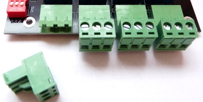
- removable terminal blocks
for easy assembly and disassembly
- relays with SPDT switch
contacts: Normally Open, Common, Normally Closed
- can directly connect to 5V/3.3V/1.8V logic signals
- separate power input for the relays to avoid glitches on the power lines of the digital circuits
- 5.5/2.1mm DC jack female
connector for relay power input, center positive (CN22)
- 4-pin 2.54mm pitch connector for logic power input and control connection (CN21)
| Board size | 100 x 80 mm (3.94 x 3.15 inch) |
| Logic supply voltage | 1.8-5.5VDC |
| Relay supply input current
required for
5V version |
635 mA @ 5V input from CN22 |
| Relay supply input current required for 12V version | 267 mA @ 12V input from CN22 |
| Relay contact ratings, resistive
load |
7A 28VDC 10A 125VAC 7A 240VAC |
| Relay contact ratings, inductive
load |
3A 120VAC 3A 28VDC |
| Relay contacts maximum voltage |
250VAC 110VDC |
| Relay contacts resistance, ON |
100mΩ max |
| Terminal block wire range |
AWG24-AWG12 |
Setup and use
- Connect the I2C signals and logic power supply to CN21
- Connect the relay power supply to CN22 jack (5VDC or 12VDC, depending on the relay voltage of the board)
The pinout for CN21
is:
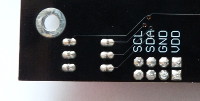
| CN21 pin |
pin name |
| 1 (square) |
VDD (logic power supply
input) |
| 2 |
GND (common power supply ground) |
| 3 |
SDA (I2C data) |
| 4 |
SCL (I2C clock) |
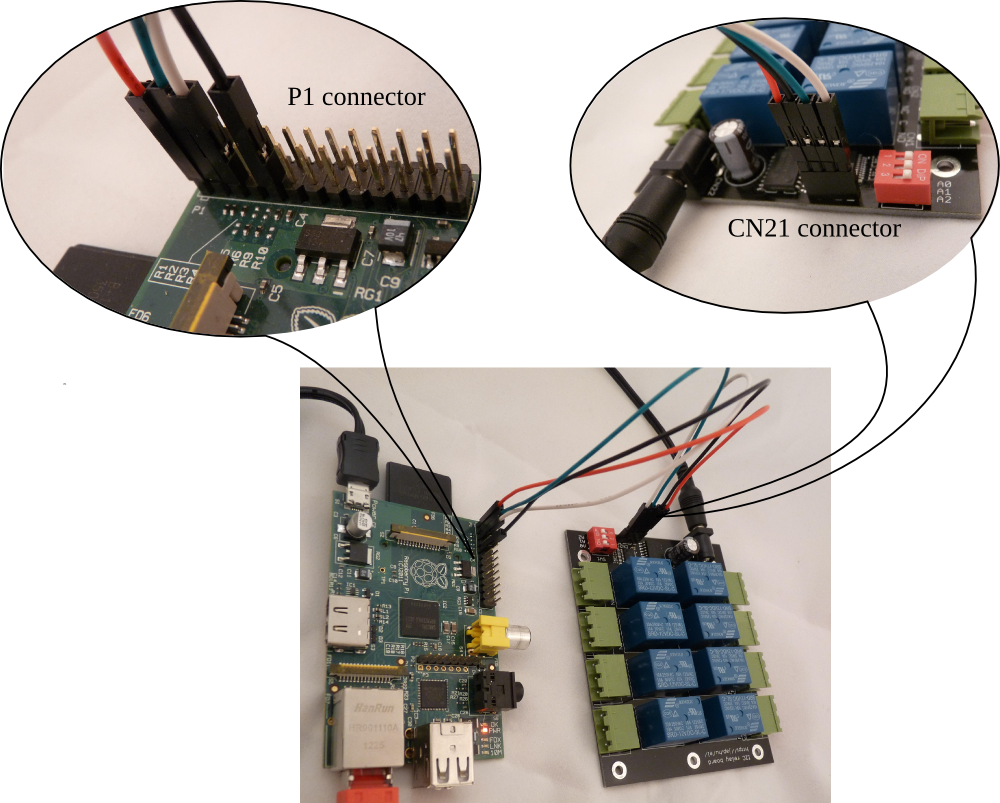
Connect the relay board to a Raspberry Pi as:
| Raspberry Pi P1 pin | relay module CN21 pin |
pin name |
| 1 |
1 (square) |
+3.3V (logic power supply
input) |
| 9 |
2 |
GND (common power supply ground) |
| 3 |
3 |
SDA (I2C data) |
| 5 |
4 |
SCL (I2C clock) |
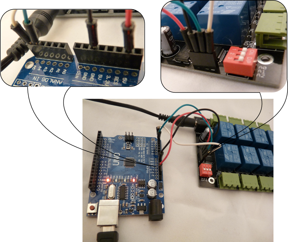
Connect the relay board to an Arduino as:
| Arduino pin |
relay module CN21 pin |
pin name |
| power 5V |
1 (square) | logic power supply input |
| power GND |
2 |
GND (common power supply ground) |
| analog 4 |
3 |
SDA (I2C data) |
| analog 5 |
4 |
SCL (I2C clock) |
Example of controlling the relays on a Raspberry Pi board:
| command line example |
explanation |
| relayctl setport 0 |
turn all 8 relays OFF |
| relayctl setport 0b00001100 |
turn relay for CN3 and CN4 ON, all others OFF |
|
relayctl setbit 0b10000000 |
turn relay for CN8 ON, don't change the state of other relays |
| relayctl clearbit 0b01000001 | turn relay for CN1 and CN7 OFF, don't change the state of other relays |
Please read the the full documentation here.
Download the support package with examples and utilities for the I2C relay board. The package contains:
| bin/linux.x86/relayctl |
relay control utility for 32-bit
x86 Linux |
| bin/raspberry/relayctl |
relay control utility for the
Raspberry Pi |
| src/arduino/relayboard_i2c.ino | example source code to control the relay board from an Arduino |
| src/i2c-tools/relayboard_i2c.sh | example shell script to control
the relay board by Linux i2c-tools |
| src/relayctl/ |
C source code for the relay control utility |