Skype:chenpeijuan2010
E-MAIL:[email removed by eBay]
What's in Box?
- 4 pcs Nema 23 stepper motor with 2.8NM 4.2A,4WIRES
- 4 pcs stepper motor driver DM542A, peak 4.2A, 128 micsteps, replacing M542
- 2 pcs Power supply 350Watts (36VDC/9.7A)
- 1 pc Breakout board & 1 pc Parallel cable
Detailed informations:
1. Nema 23 stepper motor:
Model | Step angel ( ° ) | Motor Length L(mm) | Rate Voltage (V) | Rate Current (A) | Phase Resistance ( Ω ) | Phase Inductance (mH) | Holding Torque (Nm) | Lead Wire (NO.) | Rotor Inertia (kg. c?) | Motor Weight (kg) |
23HS9442 | 1.8 | 112 | 3.78 | 4.2 | 0.9 | 3.8 | 2.8 | 4 | 0.89 | 1.7 |


2.Stepper motor driver:
1. Stepper motor driver--DM542A
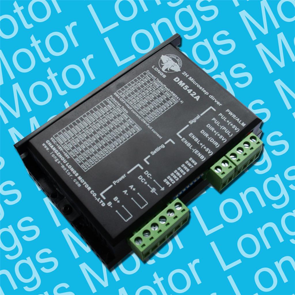
DM542A is a type of two-phase hybrid stepping motor driver, The drive voltage of which is from 18VDC to 50VDC. It is designed for use with 2-phase hybrid stepper motor of all kinds with 42mm to 86mm outside diameter and less than 4.0A phase current. This circuit that it adopts is smiliar to the circuit of servo control which enables the motor run smoothly almost without noise and vibration. Hording torque when DM542A run under high speed is also significantly higher than the other two-phase driver, what’s more, the positioning accuracy is also higher. It is widely used in middle and big size numerical control devices such as curving machine, CNC machine, and computer embroider machine, packing machines and so on.
Pin Function | Details |
PUL +,PUL- | Pulse signal, PUL+ is the positive end of pulses input pin PUL- is the negative end of pulse input pin |
DIR+,DIR- | DIR signal: DIR+ is the positive end of direction input pin DIR- is the negative end of direction input pin |
ENBL+ | Enable signal: ENBL+ is the positive end of direction input pin. This signal is used for enabling/disabling the driver. High level for enabling the driver and low level for disabling the driver. |
ENBL- | ENBL- is the negative end of direction input pin. Usually left unconnected (enabled) |
SW5 | OFF | ON | OFF | ON | OFF | ON | OFF | ON | OFF | ON | OFF | ON | OFF | ON | OFF |
SW6 | ON | OFF | OFF | ON | ON | OFF | OFF | ON | ON | OFF | OFF | ON | ON | OFF | OFF |
SW7 | ON | ON | ON | OFF | OFF | OFF | OFF | ON | ON | ON | ON | OFF | OFF | OFF | OFF |
SW8 | ON | ON | ON | ON | ON | ON | ON | OFF | OFF | OFF | OFF | OFF | OFF | OFF | OFF |
PULSE/REV | 400 | 800 | 1600 | 3200 | 6400 | 12800 | 25600 | 1000 | 2000 | 4000 | 5000 | 8000 | 10000 | 20000 | 25000 |
Output current (A) | ||||
SW1 | SW2 | SW3 | PEAK | RMS |
ON | ON | ON | 1.00 | 0.71 |
OFF | ON | ON | 1.46 | 1.04 |
ON | OFF | ON | 1.91 | 1.36 |
OFF | OFF | ON | 2.37 | 1.69 |
ON | ON | OFF | 2.84 | 2.03 |
OFF | ON | OFF | 3.31 | 2.36 |
ON | OFF | OFF | 3.76 | 2.69 |
OFF | OFF | OFF | 4.20 | 3.00 |
Motor and power pins | 1 | A+ | Motors wiring | |
2 | A- | |||
3 | B+ | |||
4 | B- | |||
5,6 | DC+ DC- | Power supply | Power supply :DC18-50VDC |
3. Power supply:
The power of this power supply is 350Watts, and the output voltage/current is 36VDC/9.7A.
4. Breakout board:
Description:
• Built in DB25 male connector.
• DB25 Output Pin:P1,P2,P3,P4,P5,P6,P7,P8,P9,P14,P16,P17.
• DB25 Input Pin: P10,P11,P12,P13,P15.
• DB25 GND Pin: P18-P25.
• Power supply: +5V DC.
• Built in C-class Optical-coupler.
• High quality with Surface-mount Tech.
Hello,thank you very much for your visit! If you want to buy more than 1set,please contact us,I will qoute you a completed price,thanks!
Moreover,we are looking for distributors in the world,if you are intrrested in our programme,please contact us!Let's grow together!!!