3.
Connections
Connections
instructions:
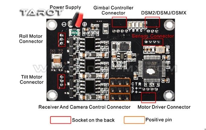
1.Power supply:
DC 7.4V~14.8V (Li-Po 3S is Recommended)
2.Gimbal controller connector:
Via USB module connected to the computer, used to adjust the gimbal controller
parameter and status monitoring.
3.Motor driver connector:
Via USB module connected to the computer, used to adjust the motor driver
module( motor poles and power), and voltage and current monitoring.
4.Receiver and camera control connector:
R: conventional receiver roll channel input
T: conventional receiver tilt channel input
C: conventional receiver stick mode channel input (rate mode and position mode)
S: S-BUS receiver or conventional receiver camera input
P: camera control servo output (Infrared camera module can be connected)
+: 5V output
-: power ground
5.DSM2/DSMJ/DSMX:
Used to connect DSM2/DSMJ/DSMX receiver
6.Roll and tilt motor connector:
Used to connect motor
7.Sensor connector:
Used to connect sensor module
5.
LED indication
Y:
Yellow,B:
Blue,R:
Red,G:
Green
|
Yellow blink 2 times |
Initialization successfully |
|
Yellow solid |
Initialization not finished, keep gimbal static |
|
Blue blink |
Receiver connected or PC software connected(normal) |
|
Blue LED solid |
Receiver not connected(normal) |
|
Red solid |
Angle out of band or error occur |
|
Green solid |
Over current,After
troubleshooting, reapply power can recover
|
6. Protection function
Reverse power
protection:
When the power is reversed, the gimbal won’t response
avoiding burning the control panel, thereby enhancing reliability.
Motor output
short circuit protection function:
When the motor output is shorted motor output PTZ control
panel will turn off and the green light is lit, thereby protecting the control
panel from burning. After the short troubleshooting, you must re-power to lift
the protection.
Angle overrun
protection function:
When the camera angle exceeds the limit, it will
automatically shut down the motor output and the red light is lit, thereby
protecting the lines laid down being wrapped broken in unexpected situations.
After the short troubleshooting, re-power or re-start the motor on the computer
side, then the gimbal can be restored.
7.
Setup instruction
Brushless gimbal system uses a
dual-processor solution (gimbal controller processor and motor driver
processor). Software interface is as follows. 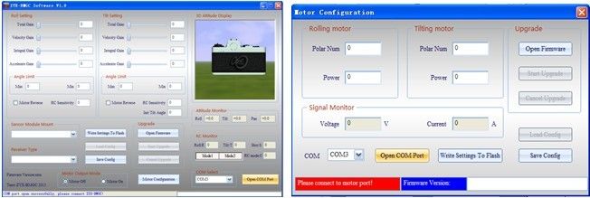
A、Gimbal
controller software UI instructions
Connect USB programmer to gimbal controller port. Open
ZYX-BMGC.exe, run ZYX-BMGC software, software interface is as follows.
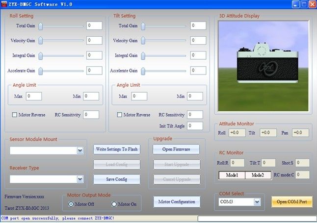
(1) Open port:
Select COM port in the software, and click “Open COM Port”. After that, you can
power on gimbal. The power supply should make gimbal work safely.
(2) Gimbal controller connection status:
After the initialization process, the status bar should show “All parameters
updated!”. This means gimbal has been connected to software successfully. Toggle
arbitrary axis of the gimbal, you should see the movement of the gimbal in 3D
attitude display on the screen. For safe configurations, when gimbal connected,
the program automatically sets motor output mode off.
(3) Sensor module mount:
You should select right sensor module mounting way at “Sensor Module Mount”
according to step1. Then, you should observe “3D Attitude Display” whether can
reflect camera’s real
motion.
(4) Receiver
type:
Connect your receiver’s connection to ZYX-GS’ receiver input
port, and select right receiver type in configuration program. When the receiver
type changed, you should click “Write Settings to Flash”, and restart ZYX-GS.
DSM2/DSMJ/DSMX
receiver type:
DSM2-1:Transmitter
is DX7 etc. (binding by 6 or 7 channels
receiver)
DSM2-2:Transmitter
is DX8, DSX9 etc. (binding by 6 or 7 channels receiver)
DSM2-3:Transmitter
is DX8, DSX9 etc. (binding by 9 channels receiver)
DSM2-4:Transmitter
is DM8, DM9 module. (binding by 6 or 7 channels receiver)
DSMJ:
Transmitter is DSMJ format. (Binding by matched receiver)
DSMX-1:Transmitter
is DX 8 etc. (11ms mode, binding by matched
receiver)
DSMX-2:Transmitter
is DX 8 etc. (22ms mode, binding by matched receiver)
(5) RC monitor:
After you select receiver type and restart gimbal, the window
will give you a real time display for all input channels.
R: roll input
channel.
T: tilt input
channel
S: camera remote
infrared shutter control channel
C: RC Mode Switch:
Mode1: stick rate
mode
Mode2: stick
position mode
(6) Angle
limits:
You can limit the roll angle and tilt angle for your need.
Roll angle limits range is -45º~45º, tilt angle limits range is -135º~90º.
NOTICE: when the attitude of the gimbal is
not in limits range, gimbal will set motor output mode off for safety. When you
configure gimbal at first time, you should set angle limits with lower values.
(7) Motor
direction:
Motor direction is selected according to the motor rotation.
(8) Initial
tilt angle:
In stick
rate mode, when the gimbal power on, the initial tilt angle is determined by
this parameter.
(9) Motor
output mode:
Motor output mode is used for keeping the gimbal safe when
configure gimbal.
Motor off mode:
gimbal shuts down motor output signal.
Motor on mode:
gimbal outputs motor signal, at this time, the gimbal stabilization works.
NOTICE:
(a) When the motor
output mode is “motor off”, you can set sensor module mounting way.
(b) When the motor
output mode is “motor on”, there are two situations gimbal will automatically
shut down motor output signal. First situation: the total gain is zero or other
three gains are zero on any axis. Second situation: current attitude of the
gimbal is not in angle limit ranges. When you need motor output, you should set
gains value non-zero, keep the gimbal level and make sure the sensor module
mounted rightly.
(10) PID
parameters adjustment:
PID parameters range is [0-500], the basic rule is the total
sensitivity can not be 0, speed sensitivity and integration sensitivity can not
both be 0. If break these rules the gimbal will turn off the motor, this can
protect gimbal and camera.
Under the same load condition, if motor power parameter is
increased, you should reduce the gimbal gains. If its value is decreased, you
should increase the gimbal gains. In guarantee the motor power under the
condition of enough, you should minimize power value for larger gains to get
better gimbal stabilization performance. Notice that reducing motor power will
affect the ability of the gimbal resisting disturbance.
Step 1.
Accelerate gain:
First, set the total gain to an appropriate value (e.g.
100), set the velocity gain and integral gain to the minimum value(e.g.
1).Secondly, increase accelerate gain gradually until the gimbal shaking. This
value is the largest accelerate gain. Finally, reduce the accelerate gain by 20%
as the final gain.
Step 2.
Velocity gain:
First, increase velocity gain gradually until the gimbal
shaking. This value is the largest velocity gain. Finally, reduce the velocity
gain by 20% as the final gain.
Step 3.
Integral gain:
First, increase integral gain gradually until the gimbal
shaking. This value is the largest integral gain. Finally, reduce the integral
gain by 20% as the final gain.
Step 4.
Fine-tune gains:
After completing the above steps, we can be appropriate to
fine-tune each gains and get better result.
(11) Write
settings to flash:
After your configuration finished, click ”Write Settings To
Flash”. When you write flash successfully, the settings are saved in gimbal.
Next time, when you restart gimbal, these settings are loaded automatically.
B. Gimbal motor driver software UI
instructions
Connect USB programmer to motor driver port. Open
ZYX-BMGC.exe; run ZYX-BMGC software, click ‘motor configuration’, the interface
of motor configuration is in the following figure.
(1)Open COM port:
Select COM port in the motor configuration, and click ‘Open COM
Port’. After that, you can power on the gimbal. The power supply
should make the gimbal work safely.
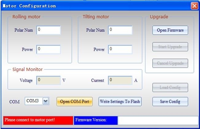
(2)Motor driver module connection status:
After motor driver module
initialization process, the status bar should show “All parameters
updated!”. This means motor driver module has been connected to
software successfully.
(3)Polar num:
Polar num is motor magnetic
pole number; this parameter will affect the reduction ratio and
highest speed of the motor. Usually, its value should be set to the
actual number of the motor. If you need special performance, its
value can be set to different from the actual pole number of the
motor.
(4)Motor power:
The range of motor power is
0%-100%, its value can be adjust according to load. Under the same
load condition, if motor power parameter is increased, you should
reduce the gimbal gains. If its value is decreased, you should
increase the gimbal gains. In guarantee the motor power under the
condition of enough, you should minimize power value for larger
gains to get better gimbal stabilization performance. Notice that
reducing motor power will affect the ability of the gimbal resisting
disturbance.
(5)Signal monitor:
Display supply voltage and
operating current of the gimbal. Voltage value displayed will be
smaller than the power supply voltage of 0.3V or so.
(6)Write settings to flash:
After your motor
configuration finished, click”Write Settings to Flash”. When you
write flash successfully, the settings are saved in gimbal. Next
time, when you restart it, these settings are loaded automatically.
8. Upgrade firmware
Notice: Because this gimbal
controller adopts double CPU solution, as main controller CPU and
motor driving CPU, there are different upgrade firmware files for
these CPUs. Before upgrading firmware, you should make sure the
hardware interface connected rightly and choosing corresponding
firmware files.
1.
Main controller firmware upgrade:
Firstly, you should connect
USB programmer to main controller port, and select right COM port,
click “Open Firmware”, choose the firmware file you want to
upgrade(do not click” Open COM Port”). After that, click “Start
Upgrade”, and then, power on the gimbal. When the progress bar
finished, firmware upgrades successfully. After firmware upgrades
finished, you can open COM port to connect gimbal to configuration
program. The new main controller firmware version can be seen in the
window.
2.
Motor driver firmware upgrade:
Firstly, you should connect
USB programmer to motor driver port, and click ‘motor configuration’
to enter into the interface of motor configuration. Select right COM
port, click “Open Firmware”, chooses the firmware file you want to
upgrade (do not click” Open COM Port”). After that, click “Start
Upgrade”, and then, power on the gimbal. When the progress bar
finished, firmware upgrades successfully. After firmware upgrade
finished, you can open COM port to connect gimbal to configuration
program. The new motor driver firmware version can be seen in the
window.