

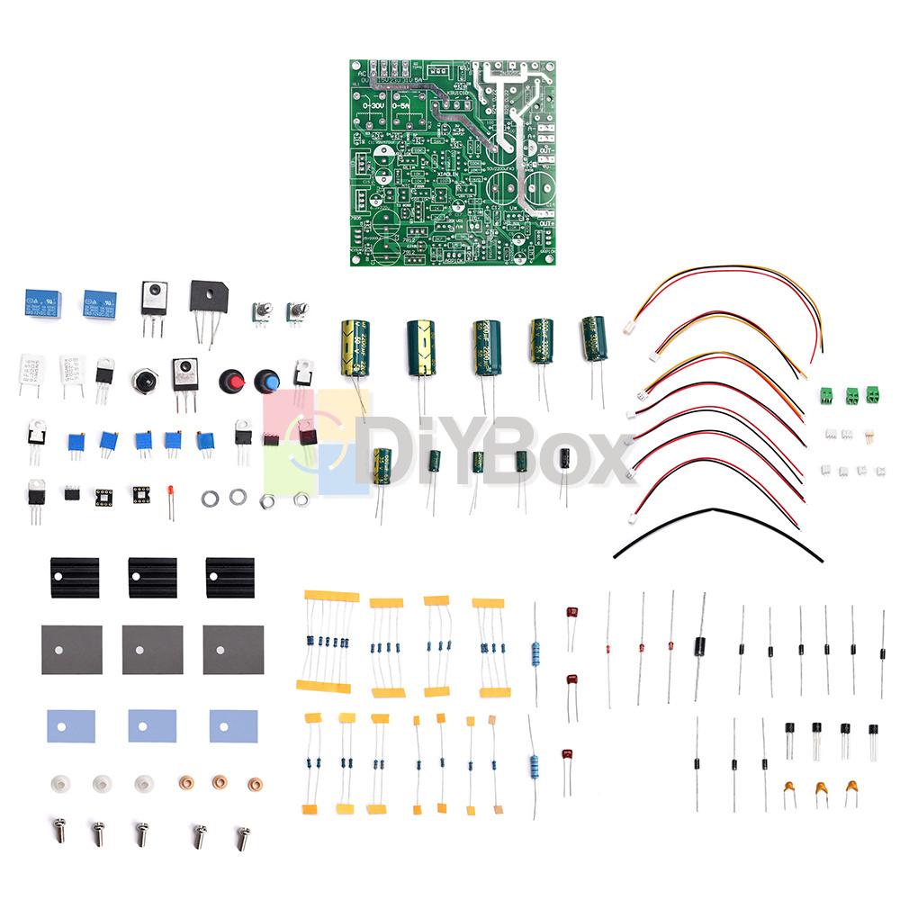
0-30V 0-5A Adjustable Power Supply Constant Voltage And Current Board Diy Kits
The old power supply can be modified to use its chassis, transformers, meters and other accessories
Linear adjustable design idea, imperfect output protection circuit, only for amateur study
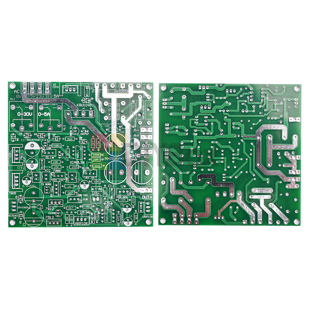
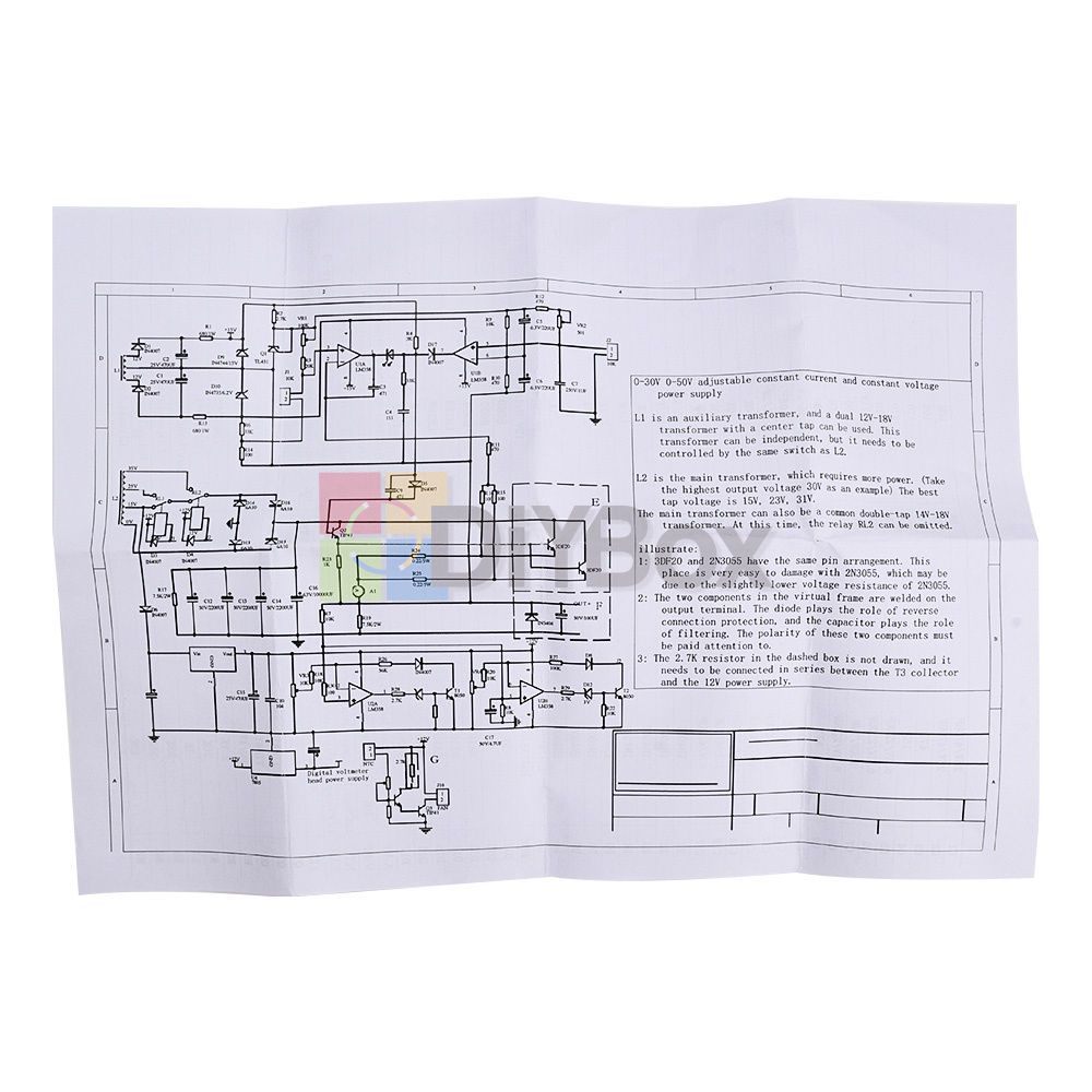
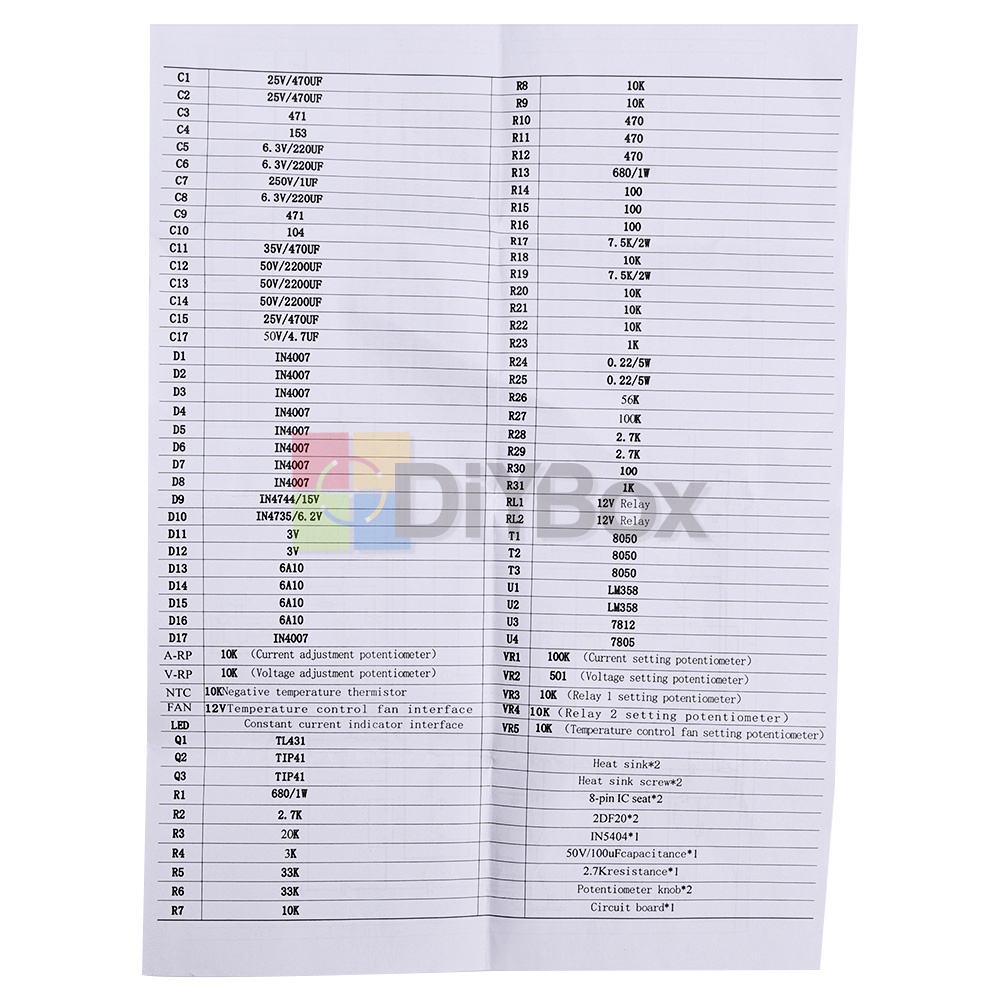
An English circuit schematic diagram and bill of materials are included with the package
Great for personal DIY
1. Please install 1A fuse for AC 220V incoming line
For the first time, try to stay away from the motherboard as far as possible! Prevent the electric cannon incident caused by various welding errors! ! !
The voltage and current potentiometers must be welded and contacted firmly! ! !
If the potentiometer is disconnected during use, there will be 30V voltage and 5A current output! ! !
The circuit component parameters are designed for 30V5A, please do not change the output voltage and current arbitrarily! ! !
(1) 150W-180W transformer (current 5A)
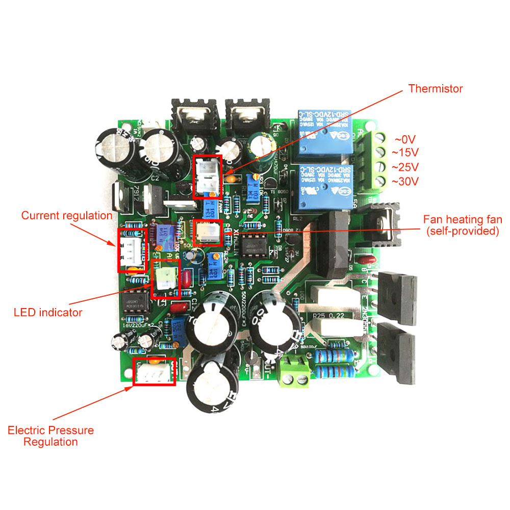
Can be customized to specify the required 3 voltage output values 15V 23V 31V ( 5A)
Add a double 12V to double 15V current 1A winding on a transformer,
The most suitable one is to disassemble the machine with a broken power supply.
Or dual 12V to dual 15V with a current of 5A for the disassembly of the power amplifier. Add a 15W small transformer.
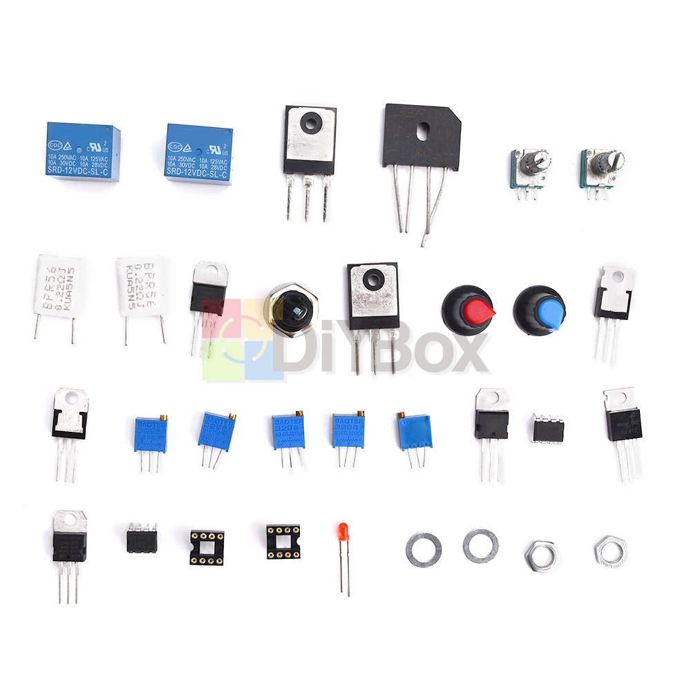
(2) Voltage and current meter head
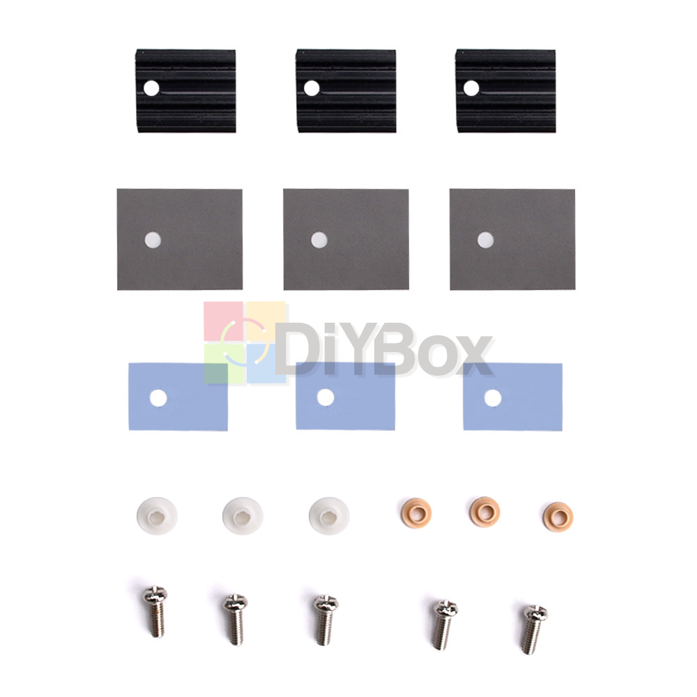
(3) 2 heat sinks for TIP3055,
(4) 12V0.2A cooling fan
(5) Chassis and red and black binding posts
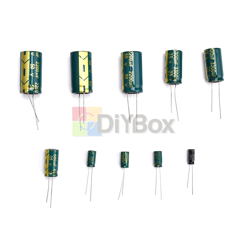
L1 is the auxiliary control power supply. It uses a center-tapped dual 12V to dual 15 voltage and current 1A transformers. The L1 winding is preferably wound on a transformer with the main power supply. The transformer at hand does not have such a winding, and a small independent transformer can also be used, but it needs to be controlled by the same switch as the L2 main transformer. L2 is the main voltage output, which requires more power. If 150W--180W outputs 30V, the suitable tap voltage is 0V-15V-23V-31V. The current is 5A (note that the voltage after rectification should be within 50V! The best is within 40V) The main voltage transformer can also choose a 150W commonly used center tap. Double 13V, double 14, double 15, the current is 5A. The 3 wires of such a 5A double output are connected to the first 3 wiring sockets in turn, and the fourth wiring socket is empty. At this time, the relay RL2 is not installed, and the normally closed 2 pins of RL2 are also short-circuited. The auxiliary control supporting electrolysis uses 25V2200*2 or 3300*2, the 7.5K in the main voltage bleeder resistance circuit diagram is replaced by 2K 3W*2, and the main voltage filtering uses 50V2200UF*3 (the total capacity should not be greater than 6600uF) to adjust the voltage and current of the two external The potentiometer can be replaced by a stable and reliable multi-turn adjustable!
Change explanation: When the load is open circuit or light load, the voltage will have a relatively large overshoot when the original circuit is shut down.
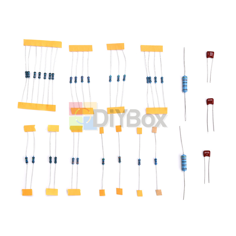
1. To reduce the bleeder resistance of the main filter capacitor, 7.5K is reduced to 2K.
2. The purpose of increasing c1 and c2 to 2200uf or 3300uf is to control the power retention time of the circuit capacitor to be longer than the power retention time of the main filter capacitor, so as to prevent the control circuit (auxiliary circuit) from losing power and causing the output voltage of the main circuit to run out of control)
Since this product is provided in a kit, the kit needs to be assembled by yourself, including electronic component soldering, circuit debugging, etc., which are complex actions that require experience.
This kit provides all components and circuit schematic diagrams, but users need to prepare transformers, casings, and voltage and ammeters by themselves! The user must understand that there may be failures due to unsuccessful assembly due to various unexpected reasons, and the user will be responsible for the losses.
Electronic products are closely related to electricity, please confirm whether to purchase or not according to your own electronic production capabilities.
This kit does not provide any technical support. Before purchasing, please refer to the schematic diagram of the kit and related debugging instructions carefully to confirm that you can complete the independent debugging before purchasing. Thank you for your cooperation!
The principle of constant voltage and constant current:
According to U=IR, R=U/I:
If R>(U/I), the power supply works normally.
If R<(U/I), I is constant, the power supply constant current is partially protected, and the output voltage drops until the condition R=(U/I) is satisfied.
The so-called constant voltage, that is, the voltage can be constant to a value, and the adjustable constant voltage, that is, the constant voltage value is adjustable.
The so-called constant current, that is, the current can be constant to a value, and the adjustable constant current, that is, the constant current value is adjustable.
Before using the adjustable constant voltage and constant current power supply, you need to set the constant current protection value, and then set the output voltage, and then start to work.
First, adjust the output voltage of the power supply to about 5V, short-circuit output, adjust the current output knob to set the protection current to the value you need, cancel the short-circuit, adjust the voltage to the required value, and connect the experimental equipment to start working.
Adjust the output voltage of the power supply to about 5V, short-circuit output, adjust the current output knob to set the protection current to 0.5A (slightly larger than the working current), cancel the short-circuit, adjust the voltage to 12V, and connect the circuit to start the experiment.
If the circuit board is placed on the metal part of the circuit during the test, the circuit is short-circuited, causing the current to increase sharply. When the current rises to 0.5A, the constant current protection part of the power supply works immediately and the output voltage drops to protect the test equipment.
After the AC voltage is filtered by the full-wave rectifier capacitor, the DC voltage is about 1.414 times that of the AC voltage.
For example, after the AC voltage of 10V is filtered by the full-wave rectifier capacitor, the DC voltage is approximately equal to 14V. Selection of relay switching point:
The AC input voltage minus 5V equals the switching voltage.
For example transformer tap 0-15V-25V-35
Then the switching voltage of the first stage is 15V-5V=10V, that is, it switches to the 25V tap at 10V.
The switching voltage of the second stage is 25V-5V=20V, that is, it switches to the 35V tap at 20V.
Whether the relay is switched or not can be judged by measuring the voltage across R17. The R17 voltage (DC) divided by 1.414 is approximately equal to the current tap voltage (AC).
After the installation is checked and correct (the capacitor and diode at the output end must be installed; the TIP3055 should be installed on a large radiator), if you do not have an ammeter connected, please short-circuit the ammeter contact "A", and then turn on the power.
Please refer to the schematic diagram:
Measure the voltage of C1 and C2, it should be normal at 12-25V.
Measure the voltage of C11, it is normal if it is less than 30V.
Measure C15 voltage, 12V is normal.
If the above voltage is abnormal, please check whether the transformer is powered, whether the tap is connected incorrectly, and whether the components are installed incorrectly. Repeat the above steps until the voltage is normal.
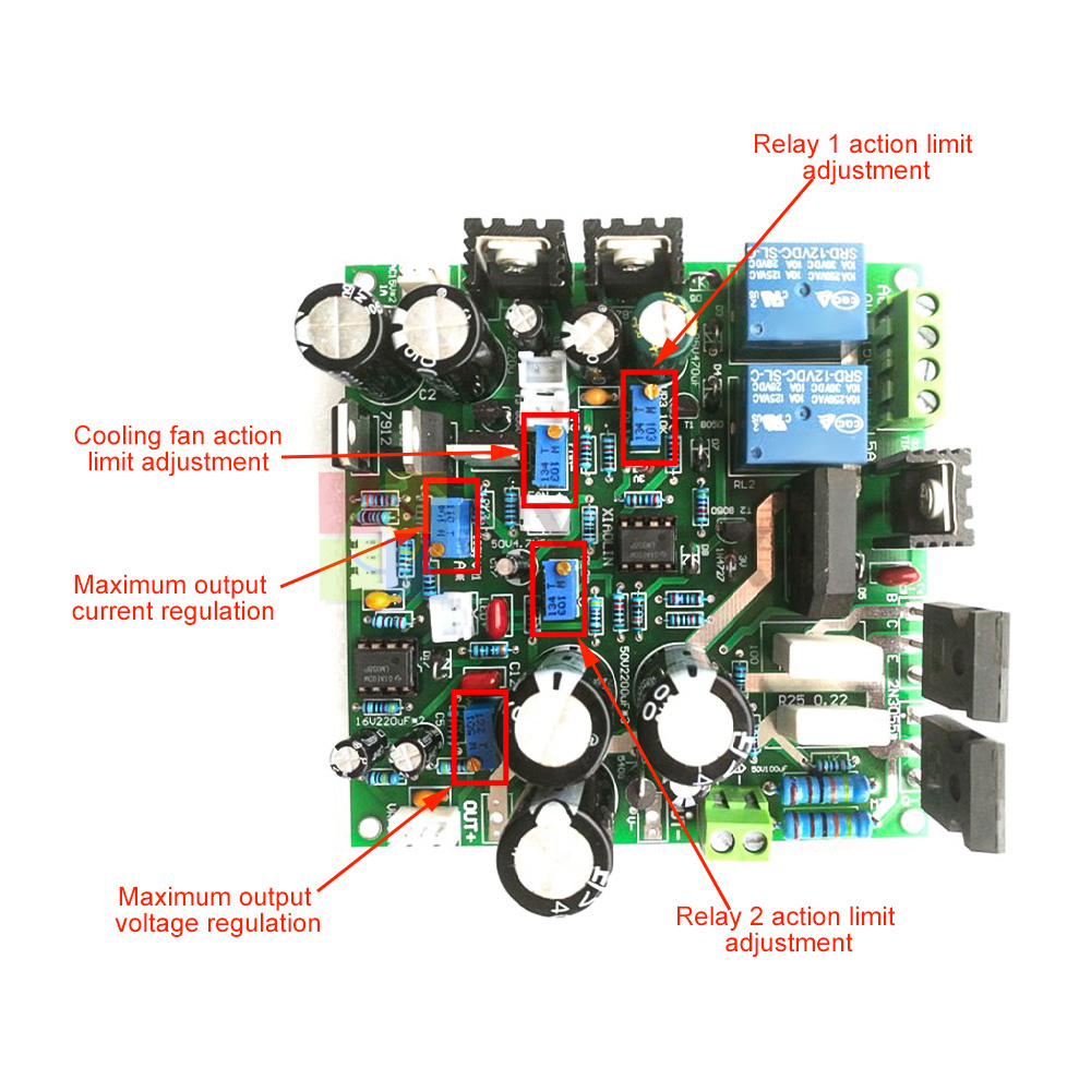
Adjust VR3 and VR4 so that the voltage of pins 2 and 6 of U2 chip is above 10V
The voltage across R17 should be the voltage after rectification and filtering by the first-stage tap of the transformer.
The A-RP current knob is adjusted to the middle, and the constant current indicator LED1 should not be on at this time.
Adjust V-RP, the voltage can be adjusted around 0-18V (R17 voltage), it is normal.
The output voltage is adjusted to the switching point voltage of the first-level relay
Adjust V-RP to see the voltage output range, adjust V-RP to make the output voltage maximum, if the maximum voltage is not 30V, adjust VR2 to make the maximum voltage 30V.
First, make sure that the adjustment tube has a large enough radiator and good heat dissipation.
Adjust the voltage to 5V, use the ammeter to tentatively short-circuit the output, and see if the constant current indicator LED1 is on?
If it does not light, there is a problem with the constant current circuit, check whether the components are installed incorrectly, and see if the LED1 is installed.
If it is on, it is short-circuited, adjust A-RP to the maximum short-circuit current, if the maximum current is not 5A, adjust VR1 to make the current to 5A.
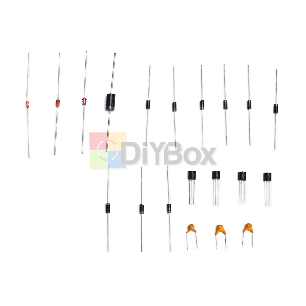
Adjustable voltage stabilized constant current power supply board parts X1
Domestic
We believe you need to get your purchases as quick as possible. As a general rule your item will be shipped within 24 hours of you purchasing it. We pack and post from Tuesday to Sunday (Mondays we are closed) but definitely get all our mail off to the post office first thing Monday morning for you. Mail gets picked up at 12pm so chances are if you buy before lunchtime your item will leave the same day.
International
Same as above but understand that depending on what part of the world you are from it does take a little longer to send, delivery can be from 7-15 working days. Also other factors to take into consideration are quarantine and customs regulations in your country. It is also a consideration that customs duties and GST/VAT may be payable at the buyers expense.
Combined Postage (for items with shipping charges):
We are more than happy to combine postage, just use the Buy it Now function in eBay (but DO NOT PAY after purchasing each item) to buy all the products you need, when you have finished request a combined invoice, we will base the shipping cost on the size, weight and your location.
* When you satisfied with our product and services please leave us positive feedback.
* If you have got the package, please confirm "Delivery on time" For us.
* If a problem occurs, contact us immediately with any email request.
* Just contact us using the " Ask the seller a question" link on eBay.
Your Satisfaction is our Priority. Our goal is to make all our customers as happy as possible while shopping with us.
For anything problem about product, price, shipping or order status, pleasecontact us via eBay message.Just contact us using the " Ask the seller a question" link on eBay.
We expect positive feedback and 5 scores DSR from you.
- We believe our items are so outstanding. We are convinced you will be happy with your Purchase.
- If you do not satisfy with our items. Please simply return to us within 30 Days in original condition. Just pay for the returned postage. Then we can issue full refund to you after the returned item arrived at our warehouse.
- Please include your eBay ID and item number with any email requests.