PWM10A MOSFET TRAILING EDGE DIMMER
UPGRADED MODEL WITH DOUBLE TEMPERARURE SENSORS
PWM 10A AC Trailing Edge Dimmer is a high-performance dimmer for 50Hz and 60Hz AC lines.
Controlled via input PWM signal for easy connection with a master device.
Designed for controlling the high power of resistive load types.
Not for inductive load types!
FEATURES:
Low cost and high performance
Not needed external power supply
PWM signal input level - 3.3V and 5.0V
PWM signal frequency up to 10kHz
Output low voltage power supply - 5.0V @ 100mA max
Optoisolation between high and low voltage side – 1000V
Input voltage range - 100…240VAC
Input AC line voltage frequency – 50Hz, 60Hz
AC line frequency autodetect function
Jumper on pcb for changing PWM input level - 3.3V/5.0V
Constant current – up to 10A
Standby power – 0.8W
Overheating protection
Dimensions - 80mm x 130mm
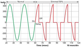
Output dimmed sine wave signal, example:
FreeDS upshield comes fully assembled with esp32, oled display and external antena.
NEW FreeDS upshield (black pcb color) is fully compatible with the old triac dimmer.
ESP32 microcontroller preflashed with the latest FreeDS firmware.
FreeDS pwm frequency should be select to 3kHz.
Wiring recommendation:
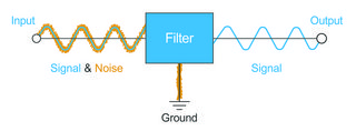
Electromagnetic interference (EMI), or electrical noise, is generated by everything from cellphones to solar flares and can make accurate signal transmission as difficult as trying to have a clear conversation in a noisy room.
To improve signal clarity in electronic circuits, should be used EMI suppression filters.
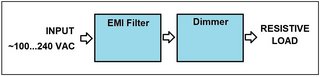
EMI filter wiring before dimmer:
Power side wiring:
Mosfet trailing edge dimmer pcb board doesn’t have protection fuse.
Recommended to use circuit breaker with protection current 10A and sensitivity level "A".
Recommended copper wire diameter at least 2.0mm (at max current 10A).
Important:
When you're operating with a current of more than 5A, set the output level slowly!
For example, if your load current is 8A and you want to set MAX output level, do it in few steps - 0%...20%...60%...100%.
Why? When the load is cold, its resistance almost equal to zero and in this case output load is like "short circuit".
APPLICATIONS:
Adjust power of heating elements
Adjust LED bulb brightness
Adjust incandescent lamp brightness
Solar panel power controlling