


1. Electrical parameters:
Input voltage: DC 24~50V input
Output current: less than 4 amperes
Output current: 1.0A~4.2A
Power consumption: power consumption: 80W; internal insurance: 6A
Temperature: working temperature -10~45℃; storage temperature -40℃~70℃
Humidity: no condensation, no water droplets
Gas: non-flammable gas and conductive dust
Weight: 200 grams
2. Control signal interface:
1. Definition of control signal
PLS+: Step pulse signal input positive terminal or positive step pulse signal input positive terminal
PLS-: Step pulse signal input negative terminal or positive step pulse signal input negative terminal
DIR+: Step direction signal input positive terminal or reverse step pulse signal input positive terminal
DIR-: Step direction signal input negative terminal or reverse step pulse signal input negative terminal
ENA+: Offline enable reset signal input positive terminal
ENA-: Offline enable reset signal input negative terminal
When the offline enable signal is valid, the drive fault is reset, any valid pulse is prohibited, the output power element of the drive is turned off, and the motor has no holding torque
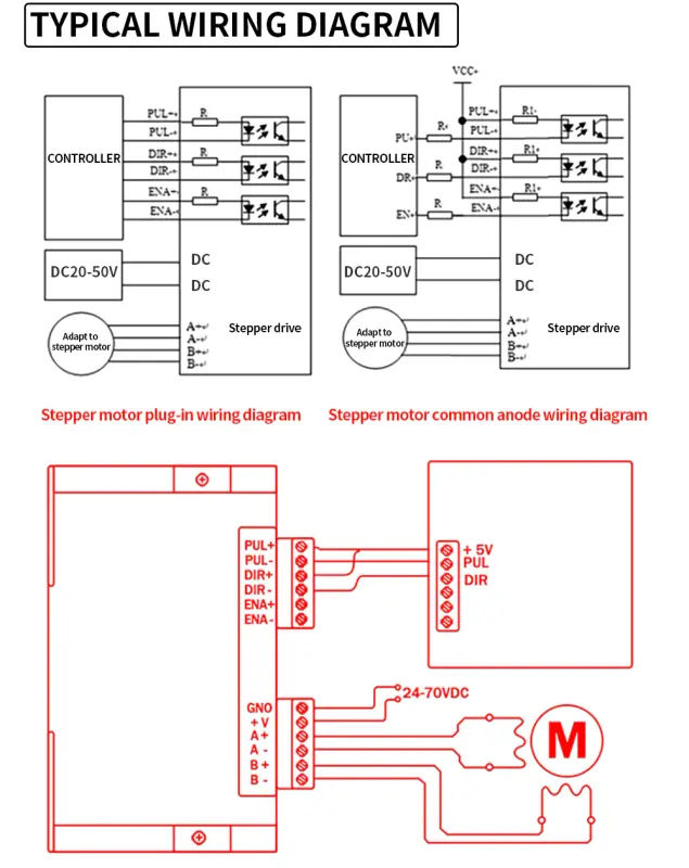
2. Control signal connection
The control signal of the host computer can be effective at high level or at low level. When high is effective, connect the negative ends of all control signals together as the signal ground, when low, connect the positive ends of all control signals together as the signal common end. Now take the open collector and PNP output as an example, the interface circuit diagram is as follows:
Drive wiring:
A complete stepper motor control system should contain stepper drives, DC power supplies and controllers (pulse sources).
The following is a typical system wiring diagram:


3. Set the output phase current
In order to drive stepper motors with different torques, the user can set the output phase current (effective value) of the drive in amperes through the DIP switches SW1, SW2, and SW3 on the drive panel, the output current corresponding to each switch position, and different models of drives The corresponding output current value is different. See the table for details.

4. Power interface:
1. +V, GND: connect the driver power supply
+V: DC power supply is positive, the power supply voltage is DC 16~50V. The high current is 5A.
GND: Negative level of DC power supply.
2. A+A-B+B-: Connect a two-phase hybrid stepping motor
The connection between the driver and the two-phase hybrid stepping motor adopts a four-wire system. The motor windings have parallel and series connection methods, and the parallel connection method has good high-speed performance, but the driver current is large (1.73 times the motor winding current).
In series connection, the driver current is equal to the motor winding current.
5. Installation:
There should be a space of 20mm around, and it should not be placed next to other heating equipment. Avoid dust, oil mist, corrosive gas, excessive humidity and strong vibration.

Troubleshooting:
1. Status light indication
RUN: Green light, on during normal operation.
ERR: Red light, on when fault occurs, short circuit between motor phases, g voltage protection and under voltage protection.
2. Failure and troubleshooting
1.LED does not light up Reason: (Wrong power connection/low power supply voltage)
Solution: 1 Check the power connection 2. Increase the power supply voltage
2.The motor does not rotate, and there is no holding torque (reason: the motor connection is incorrect/offline enable RESET signal is valid)
Solution: RESET is invalid/correct the motor connection
3. The motor does not rotate, but there is a holding torque (Reason: no pulse signal input)
Solution: adjust the pulse width and signal level
4. Wrong direction of motor rotation(Reason: wrong phase sequence of power line/wrong direction signal input)
Solution: interchange any two connecting lines and change the direction setting
5. Motor torque is too small(Reason: the phase current setting is too small, the acceleration is fast, the motor is blocked, the driver and the motor do not match)
Solution: Correctly set the phase current, reduce the acceleration value, eliminate mechanical faults, and change to a suitable driver


