
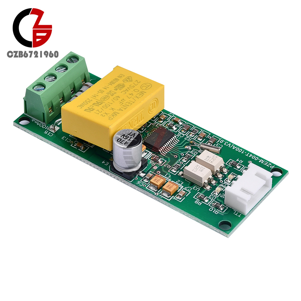
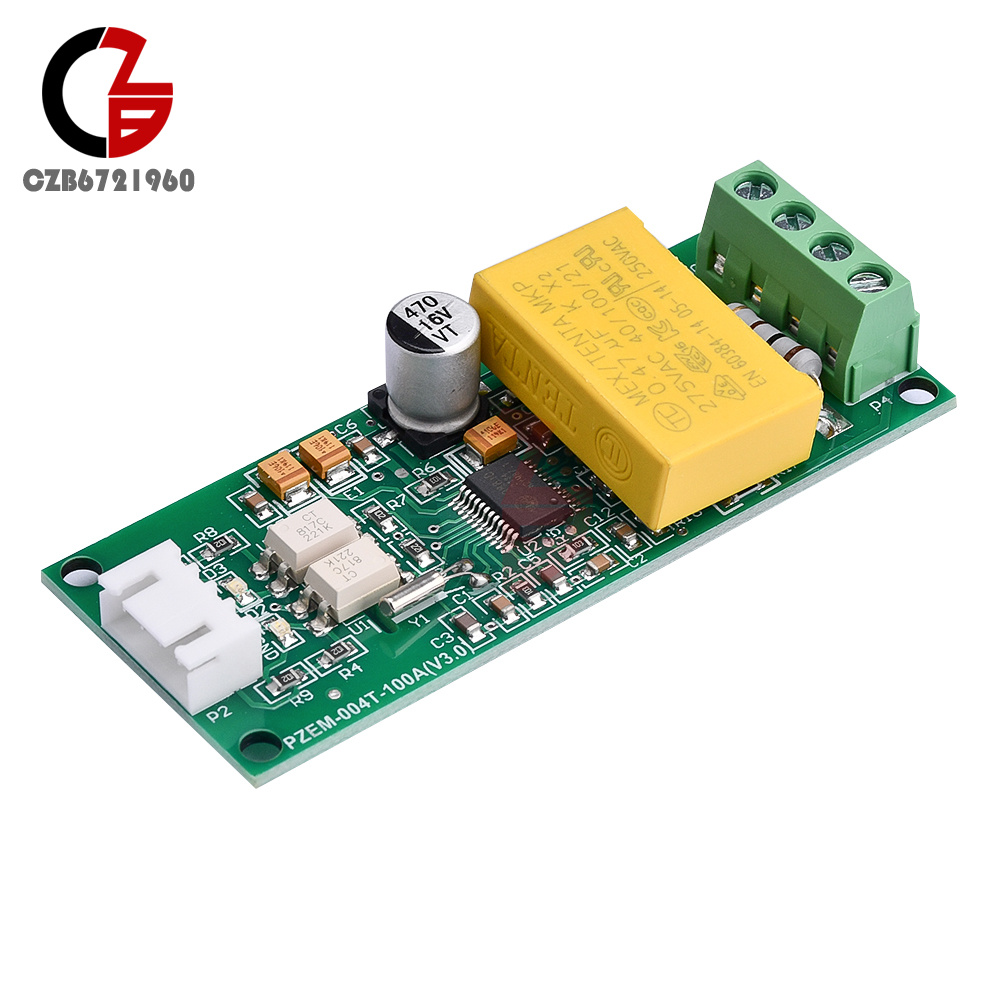
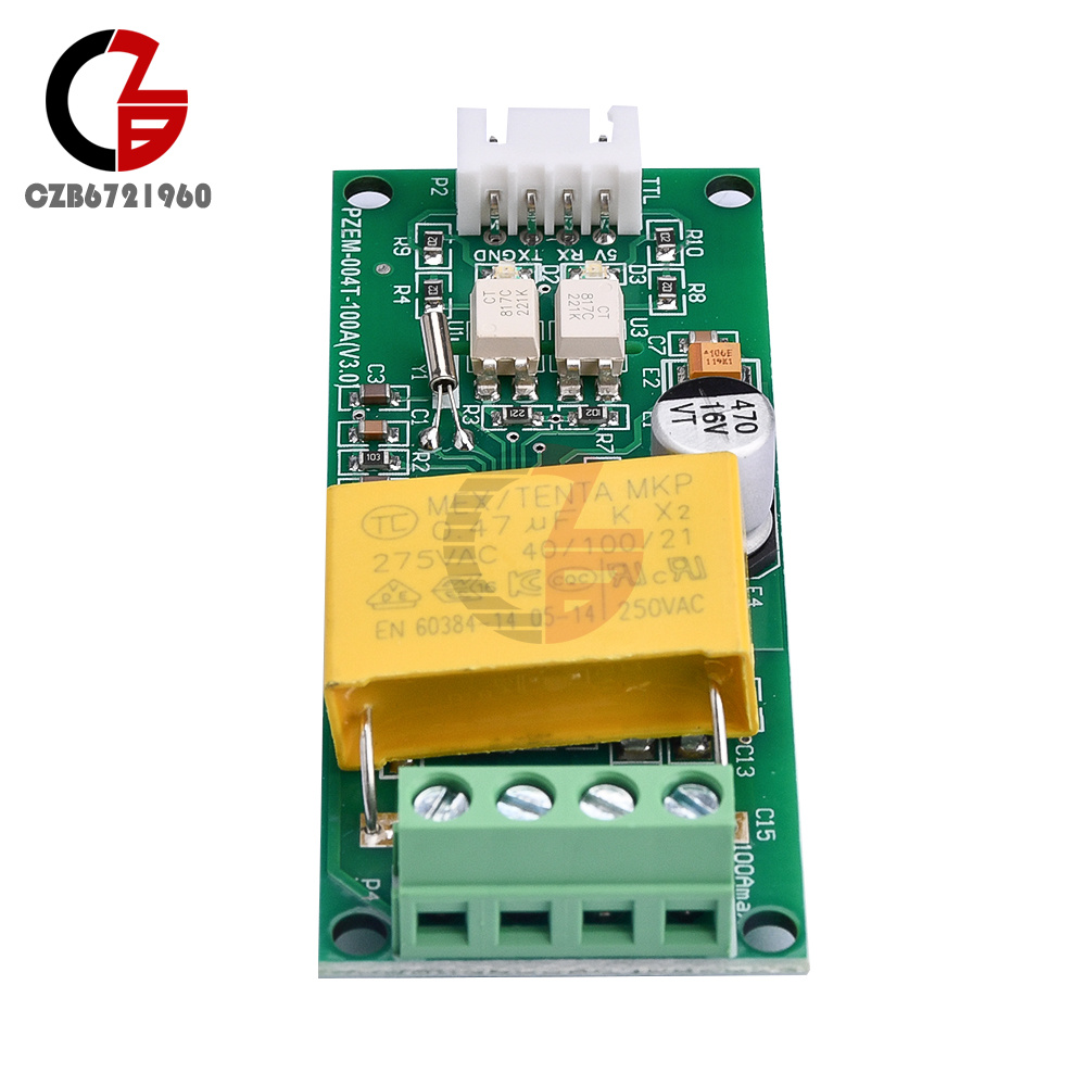
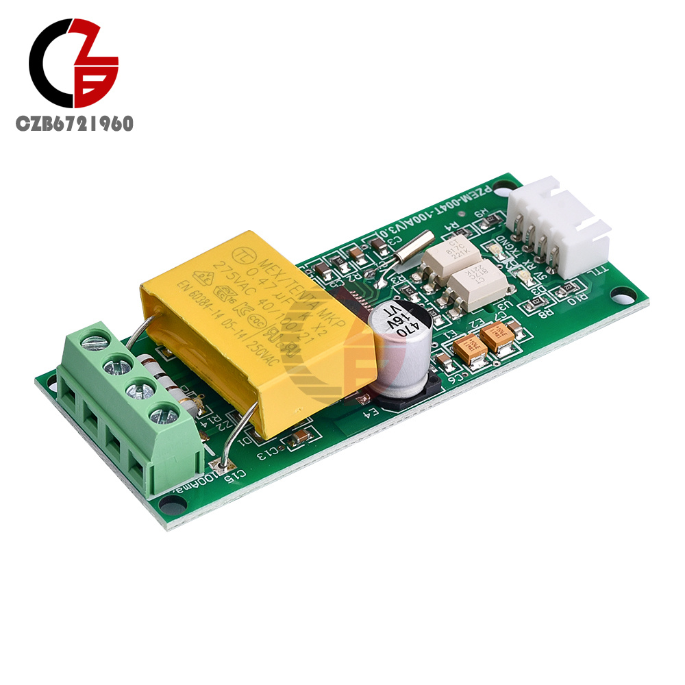
PZEM-004T AC Digital Multifunction Meter Voltage Current Test Module Board 100A
Popular


Product Introduction
Product Feature:
1. Electrical parameter measurement function (voltage, current, active power).
2. Power button clear function.
3. Power down data storage function (turned off before cumulative power savings).
4. PC display function (displaying voltage, current, and active power).
5. Serial communication function (equipped with TTL serial interface, communicating with adapter boards through various terminals, reading and setting parameters).
B. Front display screen and buttons
UI:
The PC display window consists of four windows, which are used to display the parameters of voltage, current, power, and power, as shown in the figure
Display format:
1. Power supply: measuring range 0-22kW
Within the display format of 0-0.000-9.9999, 10 kilowatts;
The display format is 10.00-22.00 at 10-22kW.
Power supply: measurement range 0-9999kWh:
10kWh within the display format of 0-0.000-9.9999;
The display format of 10.00-99.99 is between 10-100kWh;
Display formats ranging from 100.0 to 999.9 range from 100 to 1000kWh;
1000 to 9999kWh and display format from 1000 to 9999 above.
Voltage: Test range 80-260VAC:
Display format 110.0~220.0.
Current: Measurement range 0-100A:
Display format 00.00 to 99.99.
Key:
The built-in buttons on the panel are used for clear power generation functions, as shown in Figure 2.
Power reset method: Press the ZERO button for 5 seconds and then release the button! Press the clear button again, the data will be cleared and the exit fee will be cleared until the clearing is completed.
Serial communication:
The module is equipped with a TTL serial data communication interface through a serial port that can be read and set related parameters; But if you want to use USB or RS232 (such as a computer) for communication devices, you need to be equipped with different TTL adapter hardware circuit boards (for USB communication and TTL to USB adapter board; for communication with TTL RS232, RS232 adapter board is required). The specific connection details of the adapter board can be found on the diagram.
Explanation of communication:
1. Connect the hardware according to the circuit diagram.
2. After connecting the cable, a good first choice is to select the communication port of the PC software module to support the communication port COM2 COM3 COM4. Through the Device Manager, if you do not need to modify the port, do not view it on several ports.
matters needing attention:
1. This module is suitable for indoor use and not for outdoor use.
2. The applied load should not exceed the rated power.
3. The wiring should not be incorrect.
Specifications:
1. Working voltage: 80-260VAC
2. Test voltage: 80-260VAC
2. Rated power: 100A/22000W
3. Working frequency: 45-65Hz
4. Measurement accuracy: 1.0
The package includes:
Communication module bare board * 1
- We accept PayPal only. But we only Accept your Ebay Address,Please Make sure it's 100% right.
- Payment must be received in 5 business days of auction closing.
- Please leave note for your special request (e.g. Colors or Size) in PayPal when you pay the order.
- Any special request cannot be accepted after 24 hours of payment, because most of orders will be processed instantly and same day dispatched.
- We maintain high standards of excellence and strive for 100% customer satisfaction! Feedback is very important to us. We request that you contact us immediately BEFORE you give us neutral or negative feedback, so that we can satisfactorily address your concerns.
- All package need to wait 30 days(US only need 7-10 days),Please take care it.Less than 30 days,we can't take a refund.
- If the item is defect when you receive it or you are not satisfied with it, please return it within 14 days for a replacement or money back. But the items must be back in factory condition. Please contact us and double check the return address before you return it.
- If is item is defective in 12 months, you can return it to us. We will send you a new replacement after receiving the defective item.
PZEM-004T AC Digital Multifunction Meter Voltage Current Test Module Board 100A
Product Introduction
Product Feature:
1. Electrical parameter measurement function (voltage, current, active power).
2. Power button clear function.
3. Power down data storage function (turned off before cumulative power savings).
4. PC display function (displaying voltage, current, and active power).
5. Serial communication function (equipped with TTL serial interface, communicating with adapter boards through various terminals, reading and setting parameters).
B. Front display screen and buttons
UI:
The PC display window consists of four windows, which are used to display the parameters of voltage, current, power, and power, as shown in the figure
Display format:
1. Power supply: measuring range 0-22kW
Within the display format of 0-0.000-9.9999, 10 kilowatts;
The display format is 10.00-22.00 at 10-22kW.
Power supply: measurement range 0-9999kWh:
10kWh within the display format of 0-0.000-9.9999;
The display format of 10.00-99.99 is between 10-100kWh;
Display formats ranging from 100.0 to 999.9 range from 100 to 1000kWh;
1000 to 9999kWh and display format from 1000 to 9999 above.
Voltage: Test range 80-260VAC:
Display format 110.0~220.0.
Current: Measurement range 0-100A:
Display format 00.00 to 99.99.
Key:
The built-in buttons on the panel are used for clear power generation functions, as shown in Figure 2.
Power reset method: Press the ZERO button for 5 seconds and then release the button! Press the clear button again, the data will be cleared and the exit fee will be cleared until the clearing is completed.
Serial communication:
The module is equipped with a TTL serial data communication interface through a serial port that can be read and set related parameters; But if you want to use USB or RS232 (such as a computer) for communication devices, you need to be equipped with different TTL adapter hardware circuit boards (for USB communication and TTL to USB adapter board; for communication with TTL RS232, RS232 adapter board is required). The specific connection details of the adapter board can be found on the diagram.
Explanation of communication:
1. Connect the hardware according to the circuit diagram.
2. After connecting the cable, a good first choice is to select the communication port of the PC software module to support the communication port COM2 COM3 COM4. Through the Device Manager, if you do not need to modify the port, do not view it on several ports.
matters needing attention:
1. This module is suitable for indoor use and not for outdoor use.
2. The applied load should not exceed the rated power.
3. The wiring should not be incorrect.
Specifications:
1. Working voltage: 80-260VAC
2. Test voltage: 80-260VAC
2. Rated power: 100A/22000W
3. Working frequency: 45-65Hz
4. Measurement accuracy: 1.0
The package includes:
Communication module bare board * 1
- We accept PayPal only. But we only Accept your Ebay Address,Please Make sure it's 100% right.
- Payment must be received in 5 business days of auction closing.
- Please leave note for your special request (e.g. Colors or Size) in PayPal when you pay the order.
- Any special request cannot be accepted after 24 hours of payment, because most of orders will be processed instantly and same day dispatched.
- We maintain high standards of excellence and strive for 100% customer satisfaction! Feedback is very important to us. We request that you contact us immediately BEFORE you give us neutral or negative feedback, so that we can satisfactorily address your concerns.
- All package need to wait 30 days(US only need 7-10 days),Please take care it.Less than 30 days,we can't take a refund.
- If the item is defect when you receive it or you are not satisfied with it, please return it within 14 days for a replacement or money back. But the items must be back in factory condition. Please contact us and double check the return address before you return it.
- If is item is defective in 12 months, you can return it to us. We will send you a new replacement after receiving the defective item.