RF-Nano Improved for Nano V3.0 ATmega328P Board 5V 16M CH340 Integrate NRF24L01
Popular

Product Introduction
Product features:
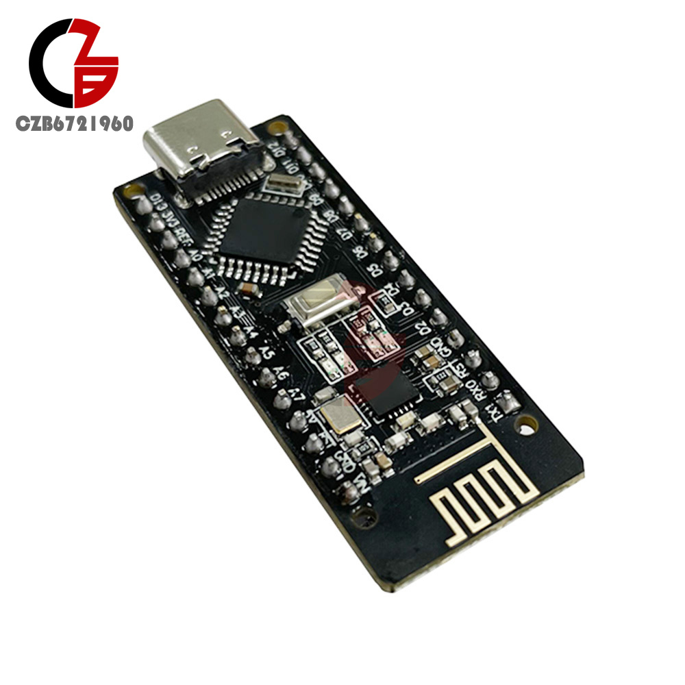
1. The improved version adopts the ATMGEA328P-AU chip in QFP32 package, which can reduce the development cost while ensuring the product function;
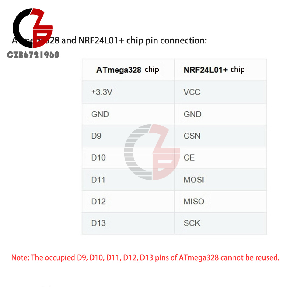
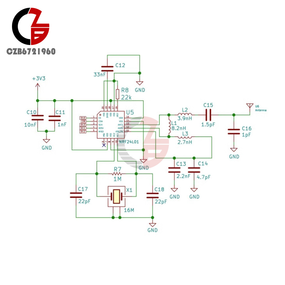
2. The board integrates a NRF24L01+ chip, which makes it have unlimited transceiver functions;.
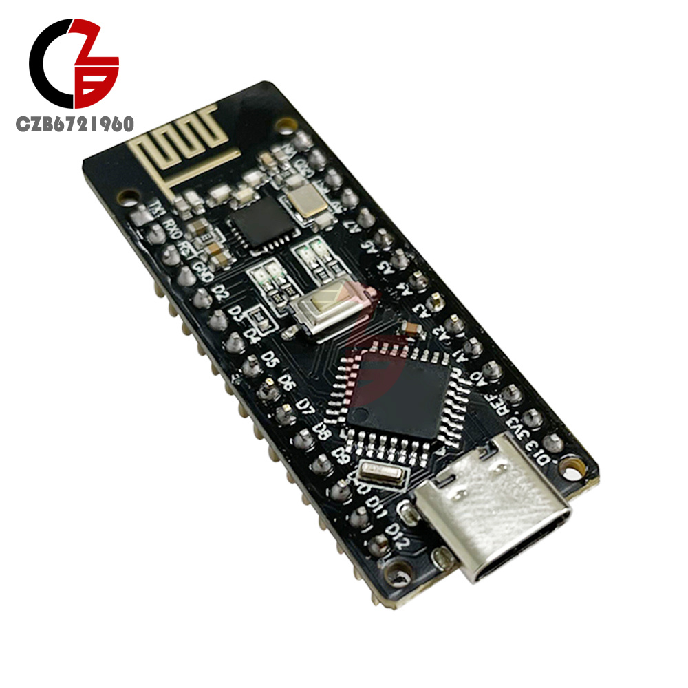
3. Nano development board and a NRF24LO1 module into one, more convenient to use, small size;
4. The pins are exactly the same as the common Nano boards, making it easy to port;
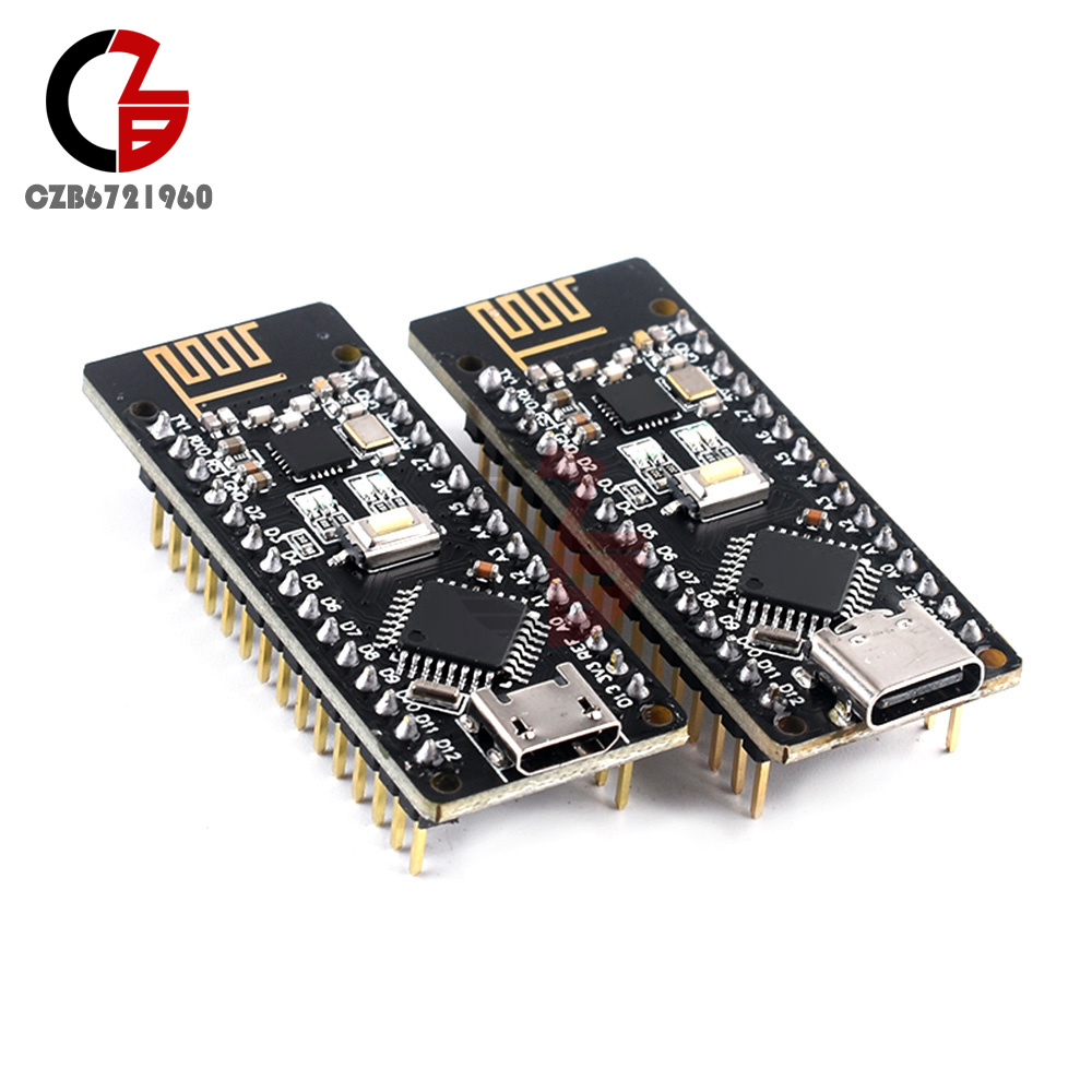
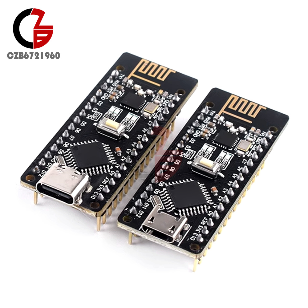
5. There are two kinds of interface options, USB-Micro and Type-C interface can be selected, can be connected to most of the products on the market to realize the interface power supply.
1. The improved version adopts the ATMGEA328P-AU chip in QFP32 package, which can reduce the development cost while ensuring the product function;
2. The board integrates a NRF24L01+ chip, which makes it have unlimited transceiver functions;.
3. Nano development board and a NRF24LO1 module into one, more convenient to use, small size;
4. The pins are exactly the same as the common Nano boards, making it easy to port;
5. There are two kinds of interface options, USB-Micro and Type-C interface can be selected, can be connected to most of the products on the market to realize the interface power supply.
Product Description.
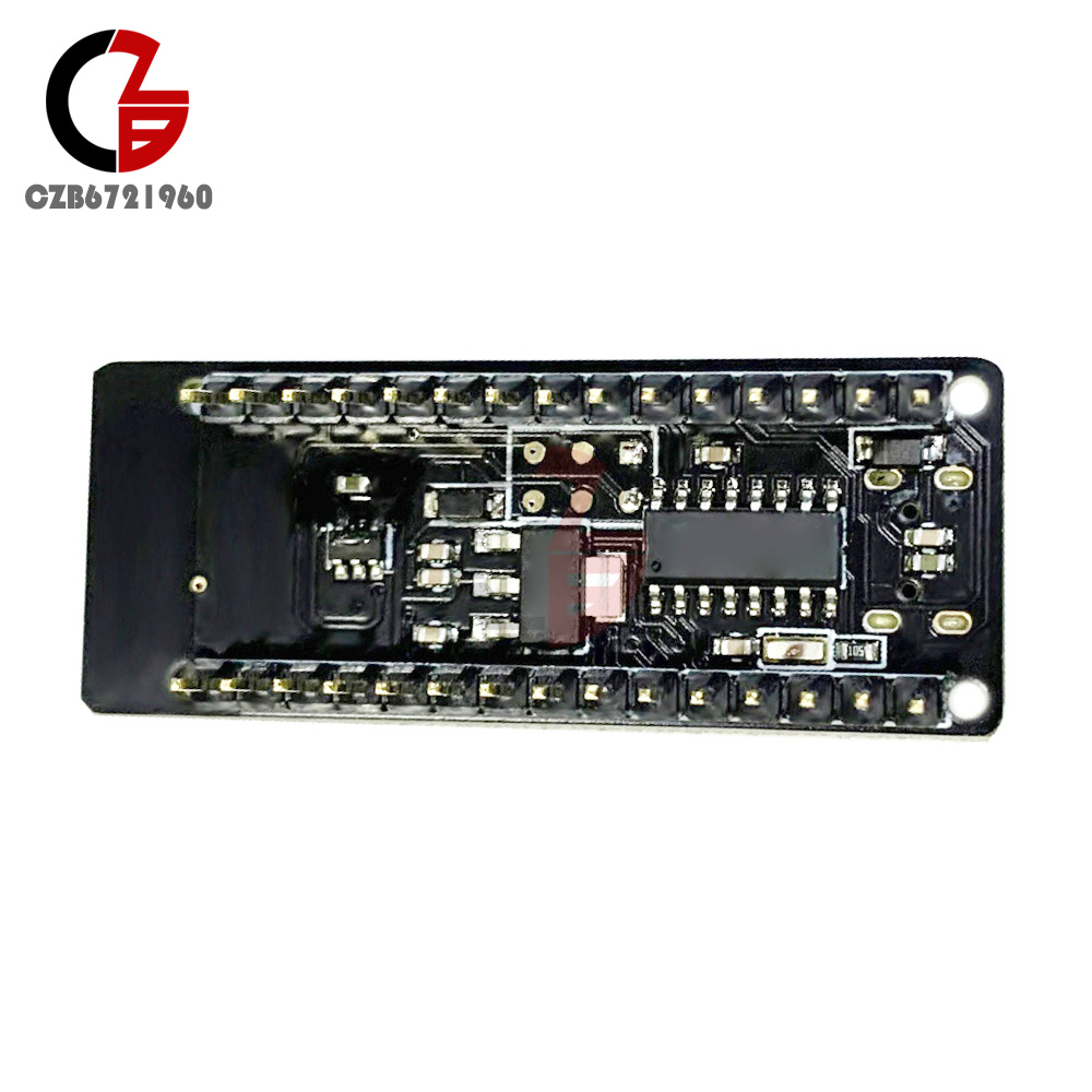
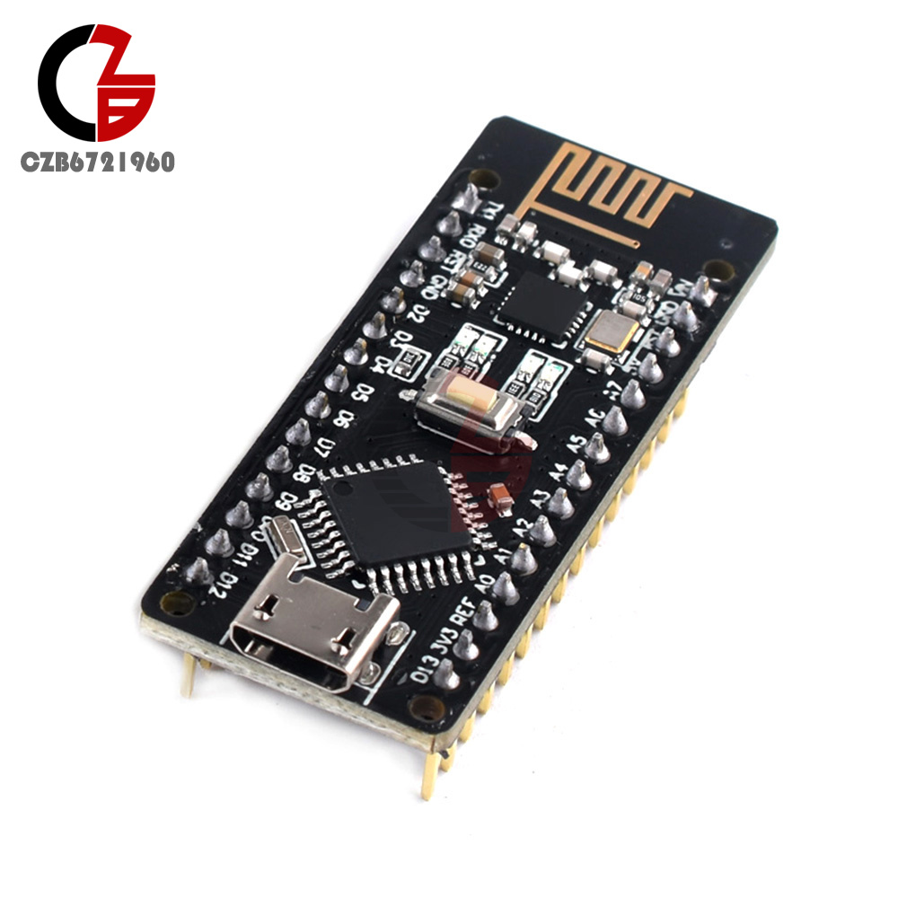
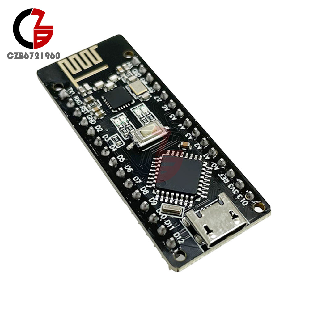
RF-NANO board integrated NRF24L01 + chip, making it has unlimited transceiver function, equivalent to a Nano development board and a NRF24LO1 module into one, more convenient to use, small size. The pins are exactly the same as those of common Nano boards, making it easy to port.
Product Parameters.
Processor Description.
The microprocessor of the module is ATmega328(Nano3.0) with USB-Micro/Type-C interface, and it also has 14 digital inputs/outputs (6 of them can be used as PWM outputs), 8 analog inputs, a 16MHz crystal oscillator, a USB port, an ICSP header and a reset button.
Processor:ATmega328
Operating Voltage:5V Input Voltage(Recommended):7-12V Input Voltage(Range): 6-20V
Digital lO pins: 14(6 of them as PWM output)(D0~D13)
Analog input pins: 6 (A0~A5)
IO pin DC current: 40mA
Flash Memory: 32KB(2KB for bootloader)
SRAM: 2KB
EEPROM: 1KB (ATmega328)
USB to Serial Chip:CH340
Operating clock: 16 MHZ
Power supply.
Power supply: USB interface power supply and external vin connection 7 ~ 12V external DC power supply
Memory.
The ATmega328 includes an on-chip 32KB Flash, of which 2KB is used for the bootloader, as well as 2KB SRAM and 1KB EEPROM.
Inputs and outputs.
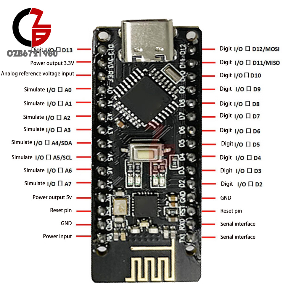
14 digital inputs and outputs: operating voltage is 5V, each one can output and access a limit current of 40mA. each one is configured with 20-50K ohm internal pull-up resistors (not connected by default). Besides, some pins have specific functions.
Serial signals Rx (No. 0), TX (No. 1): Provide serial receive signals at TTL voltage level, connected to the corresponding pins of FT232RI.
External Interrupt (No. 2 and No. 3): Trigger interrupt pin, can be set to rising edge, falling edge or simultaneous trigger.
Pulse Width Modulation PWM (3, 5, 6, 9, 10, 11): Provides six 8-bit PWM outputs.
SPI (10(SS), 11(MOSI), 12(MISO), 13(SCK)) : SPI communication interface.
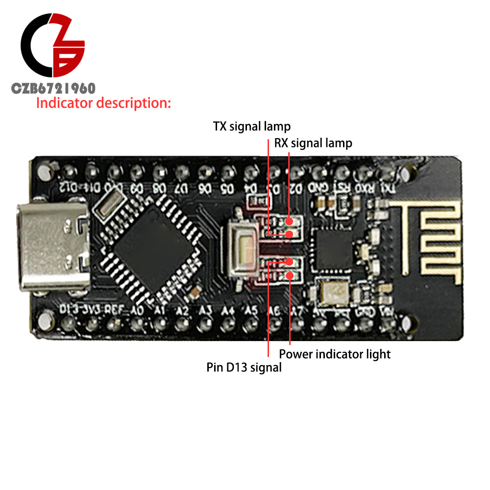
LED (No. 13) : Reserved interface specially for testing LED, LED is lit when output is high, and vice versa LED is off when output is low.
6 analog inputs A0 to A5: each with 10-bit resolution (i.e., 1024 different values for the inputs), the default input signal range is 0 to 5V, and the upper input limit can be adjusted by AREF. Besides, some pins have specific functions.
TWI interface (SDA A4 and SCL A5): supports communication interface (compatible with I2C bus).
AREF: Reference voltage for analog input signal.
Reset:Reset the microcontroller chip when the signal is low.
Communication Interface.
Serial Port: The built-in UART of ATmega328 can realize serial communication with external through digital ports 0(RX) and 1(TX).
Product List:
1X development board
- We accept PayPal only. But we only Accept your Ebay Address,Please Make sure it's 100% right.
- Payment must be received in 5 business days of auction closing.
- Please leave note for your special request (e.g. Colors or Size) in PayPal when you pay the order.
- Any special request cannot be accepted after 24 hours of payment, because most of orders will be processed instantly and same day dispatched.
- We maintain high standards of excellence and strive for 100% customer satisfaction! Feedback is very important to us. We request that you contact us immediately BEFORE you give us neutral or negative feedback, so that we can satisfactorily address your concerns.
- All package need to wait 30 days(US only need 7-10 days),Please take care it.Less than 30 days,we can't take a refund.
- If the item is defect when you receive it or you are not satisfied with it, please return it within 14 days for a replacement or money back. But the items must be back in factory condition. Please contact us and double check the return address before you return it.
- If is item is defective in 12 months, you can return it to us. We will send you a new replacement after receiving the defective item.
RF-Nano Improved for Nano V3.0 ATmega328P Board 5V 16M CH340 Integrate NRF24L01
Product Introduction
Product features:
1. The improved version adopts the ATMGEA328P-AU chip in QFP32 package, which can reduce the development cost while ensuring the product function;
2. The board integrates a NRF24L01+ chip, which makes it have unlimited transceiver functions;.
3. Nano development board and a NRF24LO1 module into one, more convenient to use, small size;
4. The pins are exactly the same as the common Nano boards, making it easy to port;
5. There are two kinds of interface options, USB-Micro and Type-C interface can be selected, can be connected to most of the products on the market to realize the interface power supply.
Product Description.
RF-NANO board integrated NRF24L01 + chip, making it has unlimited transceiver function, equivalent to a Nano development board and a NRF24LO1 module into one, more convenient to use, small size. The pins are exactly the same as those of common Nano boards, making it easy to port.
Product Parameters.
Processor Description.
The microprocessor of the module is ATmega328(Nano3.0) with USB-Micro/Type-C interface, and it also has 14 digital inputs/outputs (6 of them can be used as PWM outputs), 8 analog inputs, a 16MHz crystal oscillator, a USB port, an ICSP header and a reset button.
Processor:ATmega328
Operating Voltage:5V Input Voltage(Recommended):7-12V Input Voltage(Range): 6-20V
Digital lO pins: 14(6 of them as PWM output)(D0~D13)
Analog input pins: 6 (A0~A5)
IO pin DC current: 40mA
Flash Memory: 32KB(2KB for bootloader)
SRAM: 2KB
EEPROM: 1KB (ATmega328)
USB to Serial Chip:CH340
Operating clock: 16 MHZ
The microprocessor of the module is ATmega328(Nano3.0) with USB-Micro/Type-C interface, and it also has 14 digital inputs/outputs (6 of them can be used as PWM outputs), 8 analog inputs, a 16MHz crystal oscillator, a USB port, an ICSP header and a reset button.
Processor:ATmega328
Operating Voltage:5V Input Voltage(Recommended):7-12V Input Voltage(Range): 6-20V
Digital lO pins: 14(6 of them as PWM output)(D0~D13)
Analog input pins: 6 (A0~A5)
IO pin DC current: 40mA
Flash Memory: 32KB(2KB for bootloader)
SRAM: 2KB
EEPROM: 1KB (ATmega328)
USB to Serial Chip:CH340
Operating clock: 16 MHZ
Power supply.
Power supply: USB interface power supply and external vin connection 7 ~ 12V external DC power supply
Memory.
The ATmega328 includes an on-chip 32KB Flash, of which 2KB is used for the bootloader, as well as 2KB SRAM and 1KB EEPROM.
Inputs and outputs.
14 digital inputs and outputs: operating voltage is 5V, each one can output and access a limit current of 40mA. each one is configured with 20-50K ohm internal pull-up resistors (not connected by default). Besides, some pins have specific functions.
Serial signals Rx (No. 0), TX (No. 1): Provide serial receive signals at TTL voltage level, connected to the corresponding pins of FT232RI.
External Interrupt (No. 2 and No. 3): Trigger interrupt pin, can be set to rising edge, falling edge or simultaneous trigger.
Pulse Width Modulation PWM (3, 5, 6, 9, 10, 11): Provides six 8-bit PWM outputs.
SPI (10(SS), 11(MOSI), 12(MISO), 13(SCK)) : SPI communication interface.
LED (No. 13) : Reserved interface specially for testing LED, LED is lit when output is high, and vice versa LED is off when output is low.
6 analog inputs A0 to A5: each with 10-bit resolution (i.e., 1024 different values for the inputs), the default input signal range is 0 to 5V, and the upper input limit can be adjusted by AREF. Besides, some pins have specific functions.
TWI interface (SDA A4 and SCL A5): supports communication interface (compatible with I2C bus).
AREF: Reference voltage for analog input signal.
Reset:Reset the microcontroller chip when the signal is low.
Communication Interface.
Serial Port: The built-in UART of ATmega328 can realize serial communication with external through digital ports 0(RX) and 1(TX).
Product List:
1X development board
- We accept PayPal only. But we only Accept your Ebay Address,Please Make sure it's 100% right.
- Payment must be received in 5 business days of auction closing.
- Please leave note for your special request (e.g. Colors or Size) in PayPal when you pay the order.
- Any special request cannot be accepted after 24 hours of payment, because most of orders will be processed instantly and same day dispatched.
- We maintain high standards of excellence and strive for 100% customer satisfaction! Feedback is very important to us. We request that you contact us immediately BEFORE you give us neutral or negative feedback, so that we can satisfactorily address your concerns.
- All package need to wait 30 days(US only need 7-10 days),Please take care it.Less than 30 days,we can't take a refund.
- If the item is defect when you receive it or you are not satisfied with it, please return it within 14 days for a replacement or money back. But the items must be back in factory condition. Please contact us and double check the return address before you return it.
- If is item is defective in 12 months, you can return it to us. We will send you a new replacement after receiving the defective item.