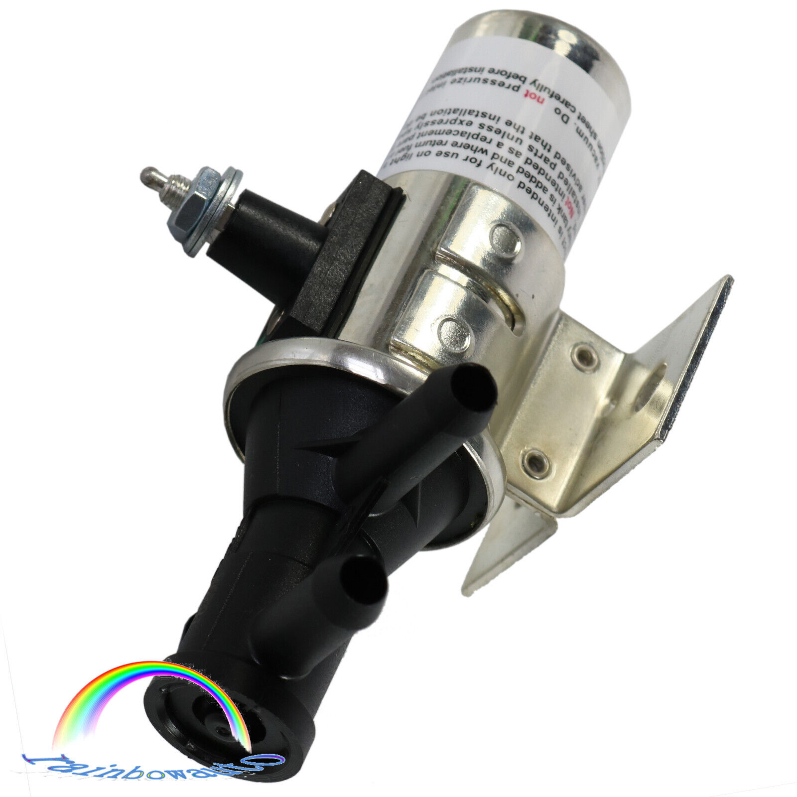
For GMC Chevrolet 3 PORT FUEL TANK SELECTOR
SWITCH VALVE FV1T FV1 DUAL Switch
GAS OR DIESEL 3 PORT FOR MAIN TANK
AUXILIARY TANK
Intended for use with the following:
Vehicles with one main and one auxiliary
fuel tank.
Vehicles without fuel return lines.
12 Volt systems.
Can be used for either gasoline or diesel
fuels.
Located between the Fuel Pump and the Fuel
Tank
3/8" Hose Barbs for use with
5/16" fuel lines.
Not for systems using in-tank fuel pumps or
pumps located between the tanks and valve.
Free Shipping To USA
One Year Warranty
Note: Fuel injections systems and diesel
systems commonly have in-tank pressure pumps. Vacuum not to exceed 8 PSI. Not
for marine applications
INSTRUCTIONS:
This Selector Valve is intended for use
with the following: • Vehicles with one main and one auxiliary fuel tank. •
Vehicles without fuel return lines. • 12 Volt systems. • Ambient temperatures
between -40°F and +180°F. The selector valve must be located between the Fuel
Pump and the Fuel Tanks. Not for systems using intank fuel pumps or pumps
located between the tanks and valve. Note: Fuel injection systems and diesel
fuel systems commonly have intank pressure pumps. • Vacuum not to exceed 8
P.S.I. • Not for marine applications.
Selector valve should be installed as shown
above. Choose a protected location near the original fuel line and mount the
selector valve to a chassis rail (horizontal valve position preferred). Bolt
valve mounting bracket to chassis using external tooth lockwashers for good
ground. Route the auxiliary tank fuel line to the selector valve as shown. Cut
the original fuel line. Using properly tightened clamps and 5/16” fuel approved
flexible hose, connect the fuel lines to the selector valve as shown. Fuel line
routing should minimize bends and have largest possible radius for better flow.
A fuel filter must be installed between each fuel tank and the selector valve
input ports to prevent foreign matter from entering the valve and causing it to
malfunction. After assembly, check the system for leaks. Choose a position on
the dash to mount the toggle selector switch. Cut the original wire from the
sending unit to the fuel gauge and connect it to the selector switch as shown.
Connect a new wire from the switch to the auxiliary tank sending unit and
another new wire to the selector valve. The connection to the selector valve
should be made by placing the properly stripped wire between the two washers
and wrapping it twice in a clockwise direction around the terminal. The nut
should be securely tightened and a coating of grease applied to prevent
corrosion. Connect a new wire from the “accessory” power to the selector toggle
switch through a 1 amp fuse. Indicator plate should be used for proper
indication of tank selected. It is normal for “Constant Duty” solenoids to run
warm. FUEL FLOW: Valve de-energized: flow is from the main fuel tank thru the
valve to the fuel pump. Valve energized: flow is from the auxiliary tank thru
the valve to the fuel pump.
1 Year Warranty:
This item have 1-year warranty.
In the event the item should fail due to
manufacturing defects during intended use, we will replace the part by free.
We only warranty cost of item parts. Any
installation or other fees are non-refundable.
Note: Any modifying the item of any kind
without contacting us will void any and all warranty coverage for this item.
Please contact us before modifying the part
so that we have the opportunity to correct the situation.
You can contact us by ebay message to get
the full text of the written warranty.
Returns:
For replacements, please notice us within 5
days after you receiving the item.
We only warranty cost of parts. Any
installation or other fees are non-refundable.
WARNING:
This product can expose you to chemicals
including Chromium (Hexavalent Compounds),
which is known to the State of California
to cause cancer, and birth defects or other reproductive harm.
For more information, go to California
goverment website, you can search California P65Warnings.