Smart Robot Car DIY Kits D2-1 Intelligent Tracking Line Automobile Parts Electronic Toy Spart Parts
Dear Sir/Madam,
Good day to you !
Thanks for referring our products.
Dear Sir/Madam, Good day to you ! Thanks for referring our products. |

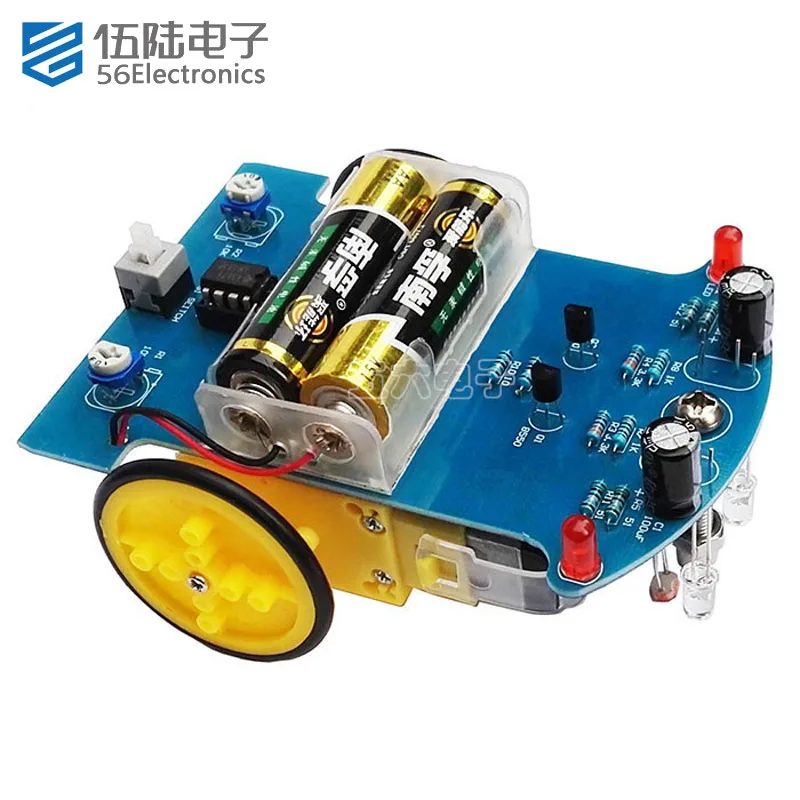


Specifications
Payment:
We accept PayPal, VISA, Master Card, American Express etc. It is fast, Easy and Safe.
Payment must be completed within 7 days.
PLEASE NOTE: S&H DOES NOT INCLUDE DUTIES, LOCATL TAXES OR ANY OTHER IMPORTATION FEES.
Please list your special requests (color, packages, etc.) in the PAYPAL NOTES SECTION when you make payment.
Shipping:
Free Shipping to Worldwide.
Orders processed within 24-48 hours of payment verification. it will take 15-25 days for delivery. but Customs will random inspection some parcel, so that's why some parcel need more than four weeks to arrive. Shipping time is only estimated and not guaranteed.
We only ship to confirmed PAYPAL addresses. Your PAYPAL address MUST MATCH your Shipping address.
Package will Shipping by E-Package with Tracking Number (Additional charges apply).
Items are shipped via China or Srilanka Post worldwide shipping with stock status.
Guarantee:
Good Good quality. Buy with confidence!
If you are not satisfied when you receive your item, please return it within 7 days for a replacement or money back. Please contact me before you return it.
Not accept returning of electronic components.
Full refund after we receive our original item, Note: Return shipping is to be paid by the Buyer.
We maintain high standards of excellence and strive for 100% customer satisfaction! Feedback is very important to us. We request that you contact us immediately BEFORE you give us neutral or negative feedback, so that we can satisfactorily address your concerns.
Thanks & Regards
Payment: We accept PayPal, VISA, Master Card, American Express etc. It is fast, Easy and Safe. Payment must be completed within 7 days. PLEASE NOTE: S&H DOES NOT INCLUDE DUTIES, LOCATL TAXES OR ANY OTHER IMPORTATION FEES. Please list your special requests (color, packages, etc.) in the PAYPAL NOTES SECTION when you make payment. Shipping: Free Shipping to Worldwide. Orders processed within 24-48 hours of payment verification. it will take 15-25 days for delivery. but Customs will random inspection some parcel, so that's why some parcel need more than four weeks to arrive. Shipping time is only estimated and not guaranteed. We only ship to confirmed PAYPAL addresses. Your PAYPAL address MUST MATCH your Shipping address. Package will Shipping by E-Package with Tracking Number (Additional charges apply). Items are shipped via China or Srilanka Post worldwide shipping with stock status. Guarantee: Good Good quality. Buy with confidence! If you are not satisfied when you receive your item, please return it within 7 days for a replacement or money back. Please contact me before you return it. Not accept returning of electronic components. Full refund after we receive our original item, Note: Return shipping is to be paid by the Buyer. We maintain high standards of excellence and strive for 100% customer satisfaction! Feedback is very important to us. We request that you contact us immediately BEFORE you give us neutral or negative feedback, so that we can satisfactorily address your concerns.
Thanks & Regards |