You are bidding for the new DiY Arduino IDE compatible micro controller-based geiger counter kit (only electronics - without the Geiger-Müller tube), with
White-on-Blue LCD.
note: You can choose either White-on-Blue (default), Black-on-Green or for extra 2USD Black-on-Green/Black-on-Orange(when backlit) LCD display
Please contact me by message is you prefer White-on-Blue or Black-on-Green/Orange-when-backlit LCD installed.
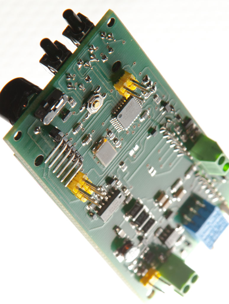
52 pcs of SMD components are already assembled and soldered on the board.
User has just to solder-in a few through-the-whole components which is easy to do even for a novice)
While retaining all the previous features and functions of the previous design,
- new version is much more compact and is mainly based on SMD components;
- has a tone mode for search of the radioactive source (like in a metal detector) switchable On or Off with an installed microswitch;
- LCD backlight is now switchable On or Off by double-clicking the "MODE" button;
- sound is now also switchable On or Off by double-clicking the "TONE-ZEROING" button;
- switching between the "Primary" and "Secondary" conversion rates is now done by long-pressing the "TONE-ZEROING" button with an few seconds indication of which rate is chosen on the LCD;
- additional potentiometer is provided to reduce the brightness of the LCD backlight (which results in essential battery power savings);
- High Voltage is now adjustable from < 100 to >1KV (1000V) which allows reliable use of high working voltage Geiger-Müller tubes;
- JTAG, i2C, TTL level Serial and battery power headers are provided for extension and connectivity purposes
---
This listing is without a Geiger-Müller tube so you need to use your own or if you don't have and need one please message me:
Currently I have in stock the following Geiger-Müller tube models:
SBT-9 (alpha beta and gamma)
SI-29BG (beta and gamma)
SBM-20 (beta and gamma)
CTC- 5 (beta and gamma)
SBT11 (alpha beta and gamma)
SBT11A (alpha beta and gamma)
SI8B (alpha beta and gamma)
SBT10 (alpha beta and gamma)
SBT10A (alpha beta and gamma)
SBM-20 (beta and gamma)
SBM-21 (beta and gamma)
SI22G (gamma)
SBT-9 (alpha beta and gamma)
SI-29BG (beta and gamma)
SI19BG (alpha beta and gamma)
SI8B (alpha beta and gamma)
This micro-controller is already preloaded with a newly feature - amended geiger kit sketch (v.11.0.2
) sketch is a free software and is available through my blog (can't give a link here because as of September 2017 eBay started to prevent linking to proprietary sites, but you can search arduino-geiger-pcb and find it in my blog).
The schematics of the device is also available but as links can no longer be given here try to look for impexeris on GitHub
(please read more about features of v.11.0.2 below on this page)
Detailed printed assembly instructions and pictures will be sent together with a kit.
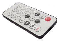
IR remote control pictured below is not a part of this listing but is available as an option for additional 3 USD
If you would like one included please ask before paying and I shall adjust the e-bay invoice.
If your Android phone has a iR transmitter you can use the free app from the Google play store:
It is called Universal TV Remote from developer called Twinone
When you install this app then download the custom remote file with your phone Internet browser:
(can't give a link here because as of September 2017 eBay started to prevent linking to proprietary sites, but you can search arduino-geiger-pcb and find it in my blog)
and open it (when asked which app to use for opening it choose the app you you have just installed)

note: the above custom remote file is when firmware which is configured to work with Sony
system remotes uploaded (this is the default configuration of firmware for boards in this listing)
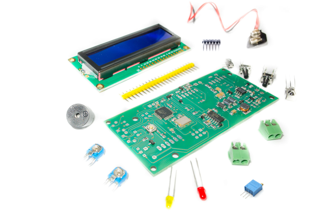
The set contains following parts:
one two-sided PCB with all the 52 pcs of SMD parts already pre-soldered and tested.
one 100Ω type 3296W multiple-turn potentiometer (for setting the High Voltage) - this potentiometer is already preset so for 400V
two 10KΩ single turn potentiometers - trimmers (for LCD contrast and LCD brightness r)
one 4kH passive electromagnetic buzzer
one yellow 3mm LED (detection indication)
one red 3mm LED (alarm threshold indication)
two 90° angle push button switches ("MODE" and "TONE-ZERO" multifunction buttons)
two KF350-2P 3.5mm terminal blocks
one 9V battery connector
one 24-pin 2,54 pitch cut-able male header for all headers
one 6-pin 90° male header
one 38kHz IR receiver
one HD44780 16x2 characters LCD module white-on-blue with backlight (backlight current draw <= 21mA). Black-on-green /w backlight is also available - please let me know your choice.
one micro-switch
I shall include a silk screen image printed on an ordinary sheet of paper.as well as schematics, and detailed instructions/advice with a number of pictures to help you assemble your geiger counter.
In case you shall have question or shall need troubleshooting assistance I shall be glad to assist.
I shall also offer a free last-resort troubleshooting support in the unlikely case you would require it (you shall just have to cover postal expenses).
note 1: the ATMEGA328-PU already contains a boot-loader and software loaded. Software is open-source (can't give a link here because as of September 2017 eBay started to prevent linking to proprietary sites, but you can search arduino-geiger-pcb and find it in my blog).
note 2: the adapted firmware version contains all multiple other features present in original v.11.0.1 Please search and refer to the DIYGeigerCounter project site for details.
note 3: kit is preprogrammed fro SBM-20 and LND-712 tubes (not a part of this listing). If you intend to use other tube please consult in advance.
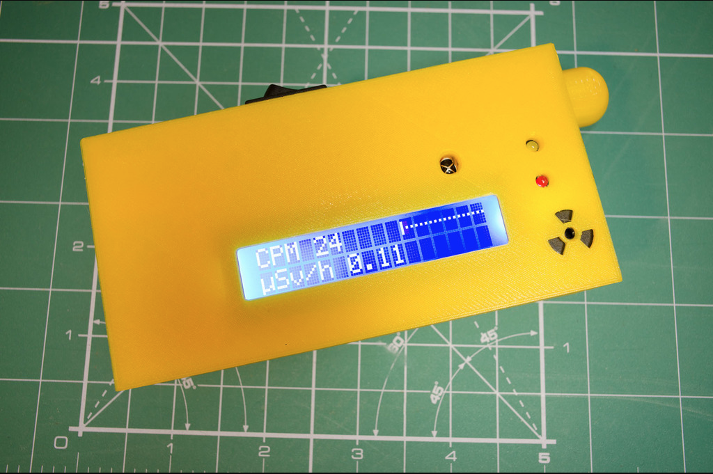
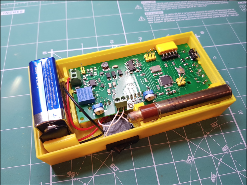
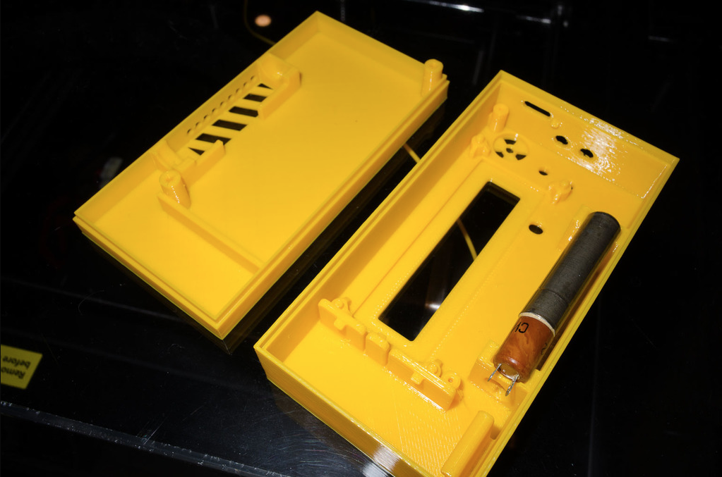
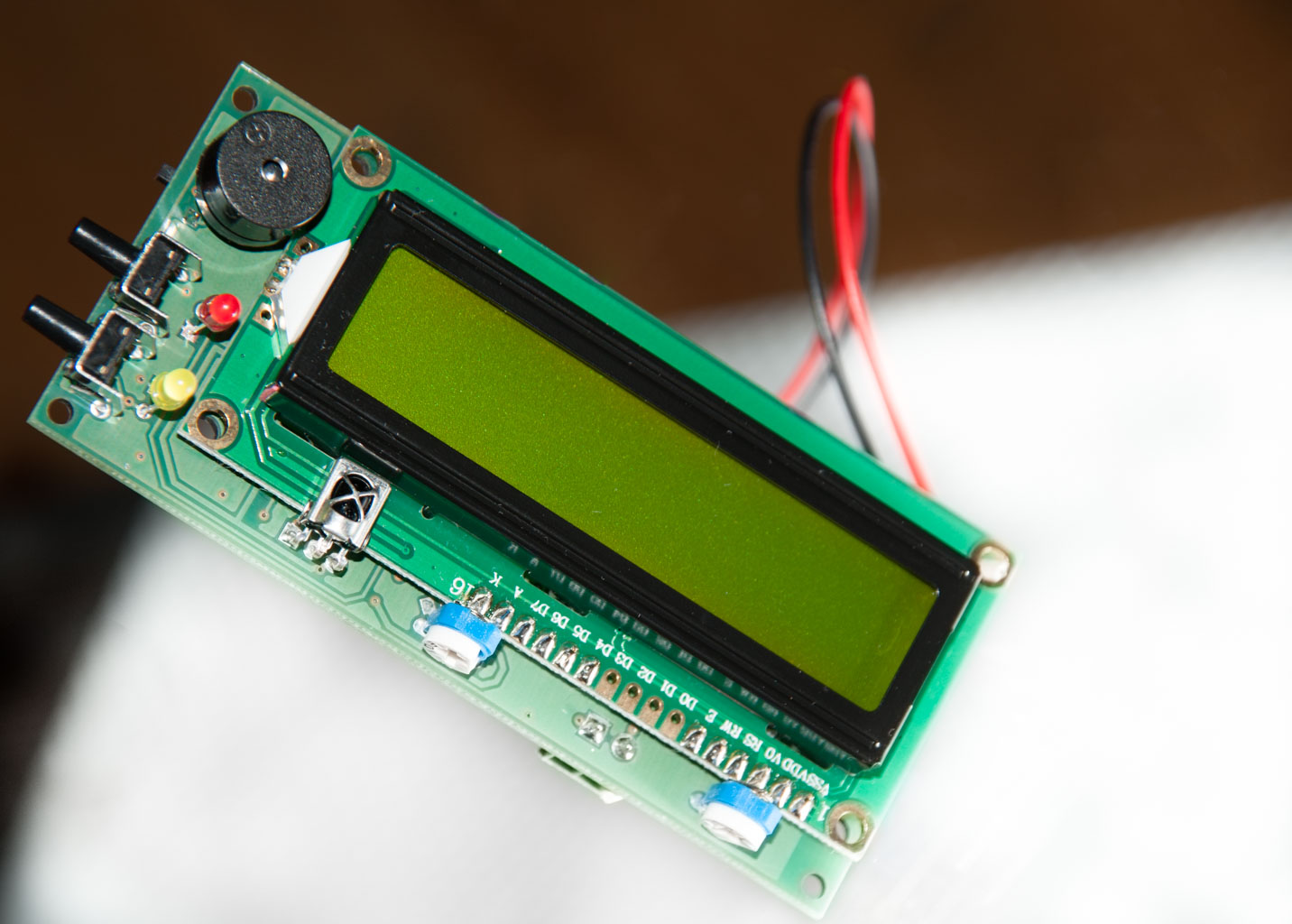
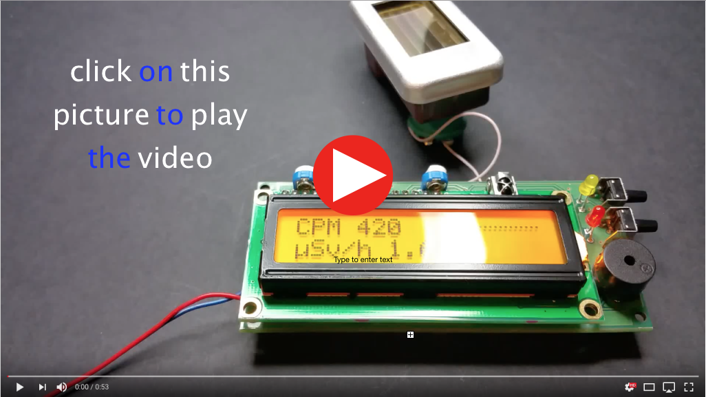
When assembled the device will look like in these pictures below (note: below pictures are provided for reference purpose only)
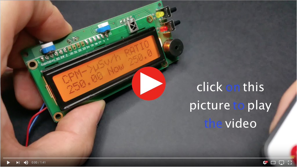
Some videos (for reference only - not a part of this listing)
---
Schematics takes its origins from a Geiger counter schematics publicly available on the Internet - on DIYGeigerCounter page and is further advanced with the final schematics freely available (as by eBay policies enforced on September 2017, proprietary links can no longer be given in listings, try to look for impexeris on GitHub)
This device is preloaded with adapted GeigerKit sketch (v.11.0.2). Sketch is a free software and is available (can't give a link here because as of September 2017 eBay started to prevent linking to proprietary sites, but you can search arduino-geiger-pcb and find it in my blog).
Counter:
can detect α, β and γ ionizing radiation.
simultaneously displays the Count Per Minute (CPM) and equivalent dose rate of radiation in μSv/h on the LCD display.
indicates detection of ionizing particles with clicking sound and flashes of the yellow LED. (has a jumper for disconnecting-muting the buzzer);
has a TTL-serial connector for connection to a computer (more information on connection to computer - below);
when connected to computer counter outputs CPM, μSv/h and power voltage data in one minute intervals;
a threshold LED lights up when preprogrammed threshold in Counts Per Minute (CPM) are exceeded.
"mpde" Push-button is used for initial threshold value setup and change of the display modes (screens) - please reed more about that below in the Software functionality description section.
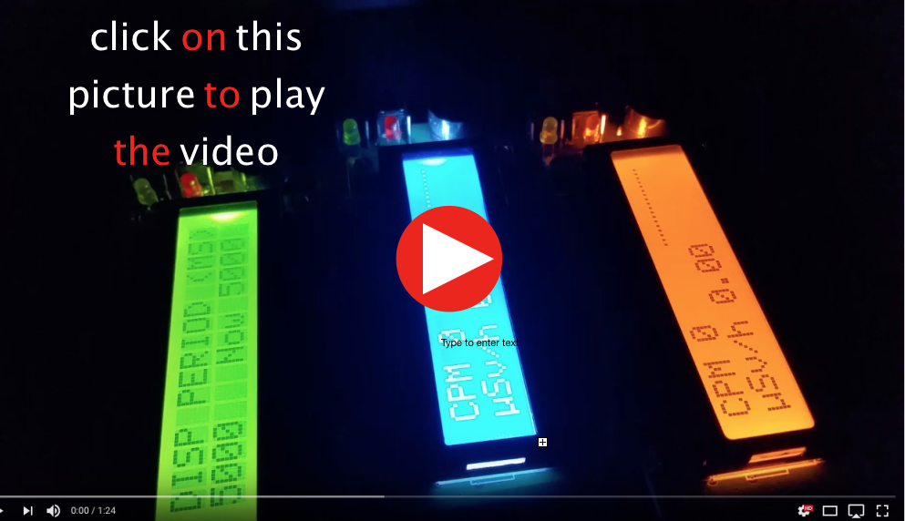
LCD display
LCD display is a 2 Line x 16 character backlit display. White-on-Blue (default), Black-on-Green or for extra 2 USD Black-on-Green/Black-on-Orange(when backlit) LCD display.
Please contact me by message is you prefer White-on-Blue or Black-on-Green/Orange-when-backlit LCD installed.
Powering the Geiger
Counter is designed to be powered from 9V battery when not connected to the computer.
It is recommended to buy a quality 6LR61 type battery.
If one desires, the whole circuit can be powered also from a 3 AA or 3 AAA batteries connected in series or 4 rechargeable batteries (rechargeable batteries are 1.2V) as circuit is actually operating at ~ 5V and there is a voltage regulator which steps down the voltage from 9 V to 5.
If you want to power the kit with lower voltage batteries 1,2 to 4,8 V please inquire. I have some step-up converters in stock.
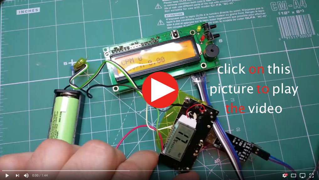
Or if you would like a rechargeable Li-Ion solution you might be interested in this post on my blog (can't give a link here because as of September 2017 eBay started to prevent linking to proprietary sites, but you can search arduino-geiger-pcb and find it in my blog).
Here's the video (for reference only - not a part of this listing)
When connected to computer (TTLSerial<>USB converter which is not a part of this listing is needed), counter can be powered throughout the TTL-Serial header and draw power from the computer.
Power consumption
With the LCD backlight being Off device draws 15 mA from the 9V battery. With LCD backlight fully ON total current drawn is around 44mA however with the 10K LCD brightness trimmer power draw can be reduced up to 18mA.
When using Tone mode, power draw can peak to 75 - 100 mA.
Connecting to a computer
Circuit has a TTL-serial connector (the 90 degree bent header) this is a serial connector, however it operates at Transistor to Transistor Voltage levels and can be connected to the computer through appropriate ttl-com port or ttl-usb adapter (TTLSerial<>USB converter which is not a part of this listing is needed). When connected to computer Counter can be a) powered from the computer b) simultaneously outputs to the standard serial terminal CPM, μSv/h and power voltage data in one minute intervals.
Software
The Software for the Counter is open-source (please ask if you need/want it in the file), developed in Arduino.cc Integrated Development Environment (IDE), which is very easy to grasp even for non-pros compared to programming in C. Therefore this counter is also good opportunity to learn about micro-controllers and change the software to your taste.
Version v.11.0.2 features:
Alarm threshold settable at power-on (retained in eeprom). Eeprom can be reset to default values by holding the "Mode" button during boot.
Alternate display (by press of the button)
A "quick response" bar graph (search aid)
Tone mode (radioactive source search aid)
Alarm (optional): When the CPM exceeds a preset value, the red threshold LED shall be lit.When the CPM drops back under the initially preset alarm threshold the LED whale go off.
The alarm threshold is configured during power up. After the first few screens you will see a "Set Alarm" prompt. To preset the alarm you have to use a push button or simply let the preset function time out (in 3 sec. of inactivity) to keep the then current setting.
Pushing the button point shall start a list of alarm settings. Push the button (or hold it down) until you find the desired setting, then release the button to set that last value. After the 600 CPM setting, the choices repeat. The possible settings increment by 10 until 100 CPM and then by 50 until the 600 CPM setting. There is also a "No Alarm" setting. The chosen setting is retained in eeprom so it does not need to be set each time.
Second Screen:
The same push button used to set the alarm is used to turn on or off the second screen. The chosen screen stays on until the button is pushed again. The first time the screen is entered, the totals will begin to accumulate from zero. After accumulation has started, reentering the mode will display the totals that have accumulated.
The second screen shows values for 1 minute and 10 minute periods. While the period is in progress (time not reached) the accumulated counts for the period are displayed. (On the 10 minute line, the elapsed time is also shown on the right side.) When a given period is complete, the format of the display changes . It then becomes the running average of CPM and uSv/h for the last 1 minute and 10 minute periods. The second screen is updated every 5 seconds.
Bar Graph:
The bar graph on the first screen shows quick changes in counts to make it easier to spot trends when surveying. It has a sample rate of 1/20 of a second.
by default Output is configured for Radiation logger software. Please see the adaptation notes on my blog (can't give a link here because as of September 2017 eBay started to prevent linking to proprietary sites, but you can search arduino-geiger-pcb. Then on the blog look for the article called "How to prepare using Radiation logger").
note: TTLSerial<>USB converter which is not a part of this listing is needed.
Convenience features:
- LCD backlight is now switchable On or Off by double-clicking the "MODE" button;
- sound is now also switchable On or Off by double-clicking the "TONE-ZEROING" button;
- switching between the "Primary" and "Secondary" conversion rates is now done by long-pressing the "TONE-ZEROING" button with an few seconds indication of which rate is chosen on the LCD;
- additional potentiometer is installed to reduce the brightness of the LCD backlight (which provides essential battery power savings);
This adapted firmware version contains multiple other features present in original v.11.0.1 Please refer to the DIYGeigerCounter site for details.
---
Dimensions
PCB 42.5mm(1.673in) x 92.9mm(3.658in) x 21.7mm(0.854in)
LCD 35.6mm(1.4in) x 78.7mm(3.1in) x 10.2mm(0.4in)