1.1 LCD can display input/output voltage, output current/output power/output capacity/output time;
1.2.
CNC adjustment, accurate and fast, can boost and lower voltage, output
voltage can be adjusted at will from 0.5-30v, limit current 0-4a can be
adjusted at will;
1.3. Anti-reverse connection protection of input end, which will not burn out;
1.4. Anti-reverse irrigation at the output end, no additional anti-reverse irrigation diode is needed to charge the battery;
1.5. The module can be set to open/close by default;
1.6.
Multiple software protection mechanisms are available, and the
protection threshold is adjustable.When the working parameters of the
module exceed the protection threshold, the output will be automatically
closed.
1.6. Output ripple is small and PI filter is available;
1.8. Thicken radiator fins.
2. Product parameters
Input voltage: 5.0-30v
Output voltage: 0.5-30v
Output current: can work stably at 3A for a long time, and can reach 4A under enhanced heat dissipation
Output power: natural heat dissipation 35W, strengthen heat dissipation 50W
Voltage display resolution: 0.01V
Current display resolution: 0.001A
Conversion efficiency: about 88%
Soft start: yes (with high power and load module may fail when starting)
Protection mechanism:
Input anti-reverse connection;
Output anti-reverse irrigation;
Input undervoltage protection (4.8-30v adjustable, default 4.8v)
Output overvoltage protection (0.5-31v adjustable, default 31V)
Output overcurrent protection 0-4.1a (adjustable, default 4.1a)
Overpower protection (0-50w adjustable, default 50W)
Overtemperature protection (80-110℃ adjustable, default 110℃)
Timeout protection (0-100h adjustable, off by default)
Super capacity protection (0-60ah adjustable, off by default)
Operating frequency: 180KHZ
Method of use
5.1.
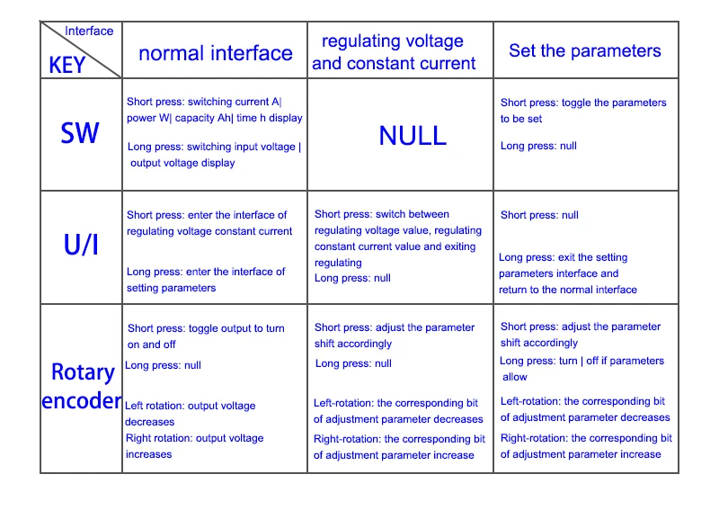
Switch display parameters -- in the normal interface, press SW to
switch the display below the display screen, and switch the display
content between current A power W capacity Ah time h.Long press SW
button to switch the uplink display on the display screen and switch the
display content between input voltage IN output voltage OUT.
5.2.
Set output voltage -- press U/I button in the normal interface to enter
the interface of setting voltage constant current.It can be seen that a
certain digit of the output voltage value is flashing. Rotate the
encoder left and right to adjust the major and minor.Short press the
rotary encoder to choose which bit of output voltage to set.After
setting, press U/I button 2 times to return to the normal interface.Or
automatically return to the normal interface after stopping operation
for 10s.
5.3.
Set constant current value (that is, the maximum current value allowed
to output by the module) -- press U/I button in the normal interface to
enter the setting voltage constant current interface.Then press U/I
button and switch to setting constant current value. You can see a bit
of the setting constant current value flashing. Rotate the rotary
encoder left and right to adjust the major and minor.Short press the
rotary encoder to choose which bit to set the constant current
value.After setting, press U/I to exit the setting voltage constant
current interface and return to the normal interface.Or automatically
return to the normal interface after stopping operation for 10s.
5.4.
Set the default on/off state of module power-on -- long press U/I in
the normal interface to enter the parameter setting interface.You can
see that it shows "OPEN OFF" or "OPEN ON". "OPEN OFF" means the output
is turned OFF by default when power is ON, and "OPEN ON" means the
output is turned ON by default when power is ON.Long press rotate
encoder to switch two states.After setting, long press U/I to return to
the normal interface.
5.5.
Setting of protection parameters on state and threshold -- long press
U/I to enter the parameter setting interface in the normal
interface.Press SW until the protection you want appears.LUP --
undervoltage protection threshold;OUP -- overvoltage protection
threshold;OCP -- overcurrent protection threshold;OPP -- over power
protection threshold;OAP -- ultra-capacity protection threshold;OHP
timeout protection threshold;OTP -- overtemperature protection
threshold.Short press rotate encoder to select which bit you want to set
the protection parameter.Long press the rotary encoder to set the
protection parameters on or off (only timeout protection and
supercapacity protection can be set to turn on/off, and other protection
parameters are turned on by default.).Rotate the encoder left and right
to make the parameters bigger and smaller.After setting, long press U/I
to return to the normal interface.
5.6.
Calibration voltage and current -- press U/I button to enter the
parameter setting interface under normal interface.Press SW until a
parameter interface with CAL appears.The calibration input voltage
interface with the symbol CAL+IN+V;The calibration output voltage
interface with the symbol CAL+OUT+V;The calibration output current
interface with the symbol CAL+OUT+A.Rotate the encoder left and right to
adjust the size of parameters.After the adjustment is completed, long
press the rotary encoder to confirm the adjustment is completed, and the
parameter value is no longer flashing.Long press U/I to return to the
normal interface.
Note:
in order to ensure the accuracy of calibration, calibration voltage --
above 12V can only be started;Calibration current - start calibration
only when the current is above 1A.
Cautions
7.1. Short connection between input IN and output OUT of the module is forbidden, or the constant current function will fail.
7.2. Please ensure that the power moment of the power supply exceeds the required power of the output load!
7.3.
If the module wants to output with full load, the input voltage should
be above 8V. When the input voltage is 5V, the output power is about
15W.The maximum module current value is 4A, subject to the maximum
output power, such as 17V, the current should not be greater than 2A.
7.4. When this module is used over 3A and 35W, please strengthen heat dissipation!!!
7.5.
The module has input undervoltage protection function, which is about
4.8v by default (it can be set), and the output will be automatically
disconnected after the value is lower than this value (note that the
voltage at the module port is lower than the undervoltage protection
threshold, and when the input current is relatively large, do not ignore
the partial voltage on the input wire).