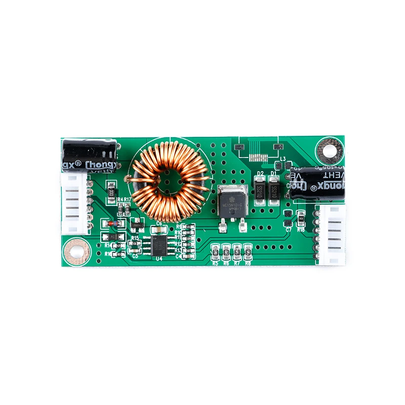
LED LCD Universal TV Backlight Constant Current Backlight Lamp Driver Board Boost Step Up Module 10.8-24V to 15-80V 14-37 Inch
Limit parameters:
At 24V input: Vout=75V Iout=720mA or maximum 60W
At 12V input: Vout=75V Iout=400mA or maximum 30W
The limit parameter refers to the maximum endurance of the product in the application process. Please use it below the limit parameter in actual use to ensure the reliability of the product.
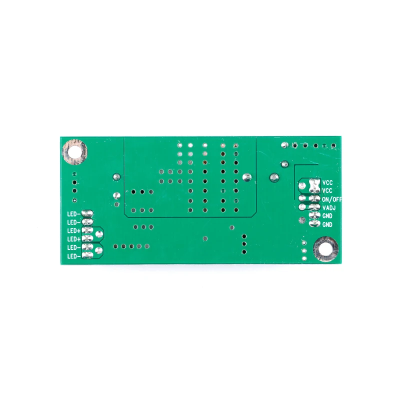
The Chinese and English codes of common electronic symbols for backlight panels are as follows:
1.VCC: positive power supply voltage, circuit power supply voltage (voltage is usually 12V or 24V)
2. ON/OFF, ON, EN, ON_BL, etc.: switch pin, switch signal pin (the voltage range is usually between 2.5V-5V)
3. PWM, PDIM, VDAJ, BL-PWM, etc.: brightness adjustment foot or dimming foot. (There are two modes for dimming, one is digital mode-PWM (the voltage of the signal is usually 3.3V), the other is analog dimming-DC (the voltage of the signal is 0-3.3V/0-5V)
PWM is called pulse width adjustment. It generates a rectangular square wave signal, the frequency is generally 200HZ-2KHZ, and the voltage amplitude is usually 3.3V. PDIM is an abbreviation for English, and Dim means dark. The vocabulary roughly means "brightness". Analog dimming is carried out by DC voltage, and it is usually used to directly provide 0V-5V DC voltage to the adjusting pin to control the brightness. )
GND: Ground (negative power supply)
LED+: Light-emitting diode (light bar) anode
LED-: light-emitting diode (light bar) cathode
The above symbols include most commonly used codes for LCD motherboards and backlight boards. When connecting, you can connect them according to their respective codes.
Common problem:
Question 1: Can the constant current driver board of a certain size TV be used instead?
Answer: As long as the working voltage of the light bar is below 80V, regardless of the size of the TV, this product can light it. Note: What is said here is just lighting, not that it is suitable. If you need an exact answer, the best way is to provide the backlight module parameters of the panel (the working voltage of the light bar, the rated current, etc.). If we can provide accurate data, we can do a "personal customization" service.
Then again, what if it is impossible to determine the voltage of the light bar? At this time, a very simple method is to find the constant current driver board on the original machine and see what is the withstand voltage of the output filter electrolytic capacitor? If it is 100V withstand voltage, it means that the voltage of the light bar will not exceed 80V, then my product can be lighted up, just take a photo decisively.
After knowing the situation where the voltage can be turned on, there is another issue that needs to be paid attention to is the current. The crystal element size of the LED lamp beads determines the rated current it needs, but for various reasons, the module factory will choose a variety of different specifications of lamp beads, resulting in a variety of different rated operating currents. To solve this problem, we suggest that if the model is 26 inches or more, use our standard parameter: constant current 480mA, if it is less than 24 inches, reduce the current to half, that is, 240mA. Here we have to explain the actual problem: 480MA is not to say that it is suitable for all screens of 26 inches or more, but to choose an approximate value for the situation where the accurate parameters cannot be determined. According to the data returned by many users, most of this current is suitable, but occasionally there will be over-brightness. At this time, the easiest way is to solve it through the dimming function foot and connect the dimming foot After Vadj, turn the brightness down.
About installation issues:
Question 1: Can't light up after installation?
1. Check if the polarity of the connecting wire is correct? Whether the LED positive and negative poles are correct.
2. Measure the power supply voltage to see if there is any voltage on the board. When the machine is turned on, measure whether the LED+ has boosted voltage, which is generally higher than the VCC voltage.
3. If there is no boost, please measure whether the ON pin has voltage, the normal voltage should be about 3.3V.
4. If the above conditions are normal, then measure the resistance value of the series connection between LED and GND when the power is turned off. Normally it should be a small resistance value below 2 ohms.
After the above steps are checked, all that is left is that the problem may be the LED light bar.
Question 2: The machine is bright, but the brightness is not enough?
First, use the remote control to adjust the brightness to the brightest to see the effect. If it is still not bright enough, then measure the PDIM pin. If the voltage is always higher than 4V through the adjustment, you need to change the low voltage by other means, just hang that pin directly First, if the brightness can meet the requirements, the brightness requirement can be achieved by changing the low pin voltage.
If the brightness is not enough by disconnecting the pin, you need to increase the brightness by other means.