
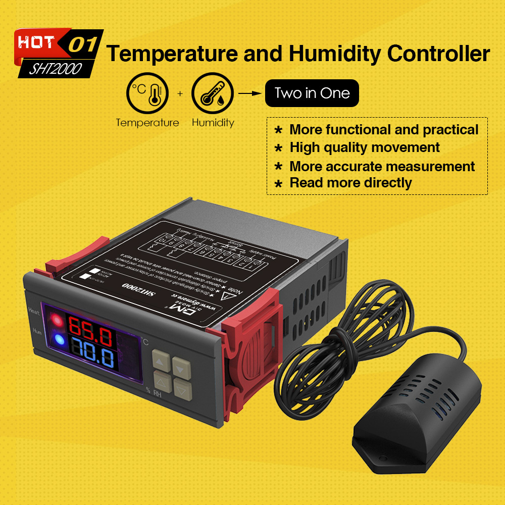
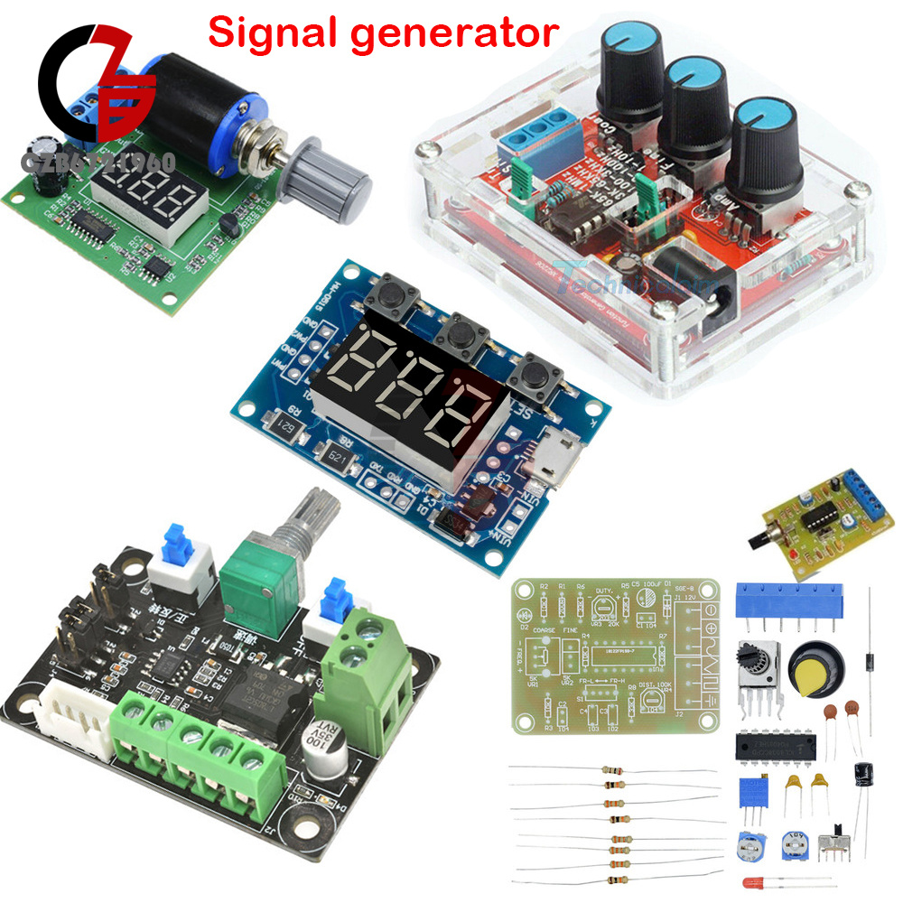
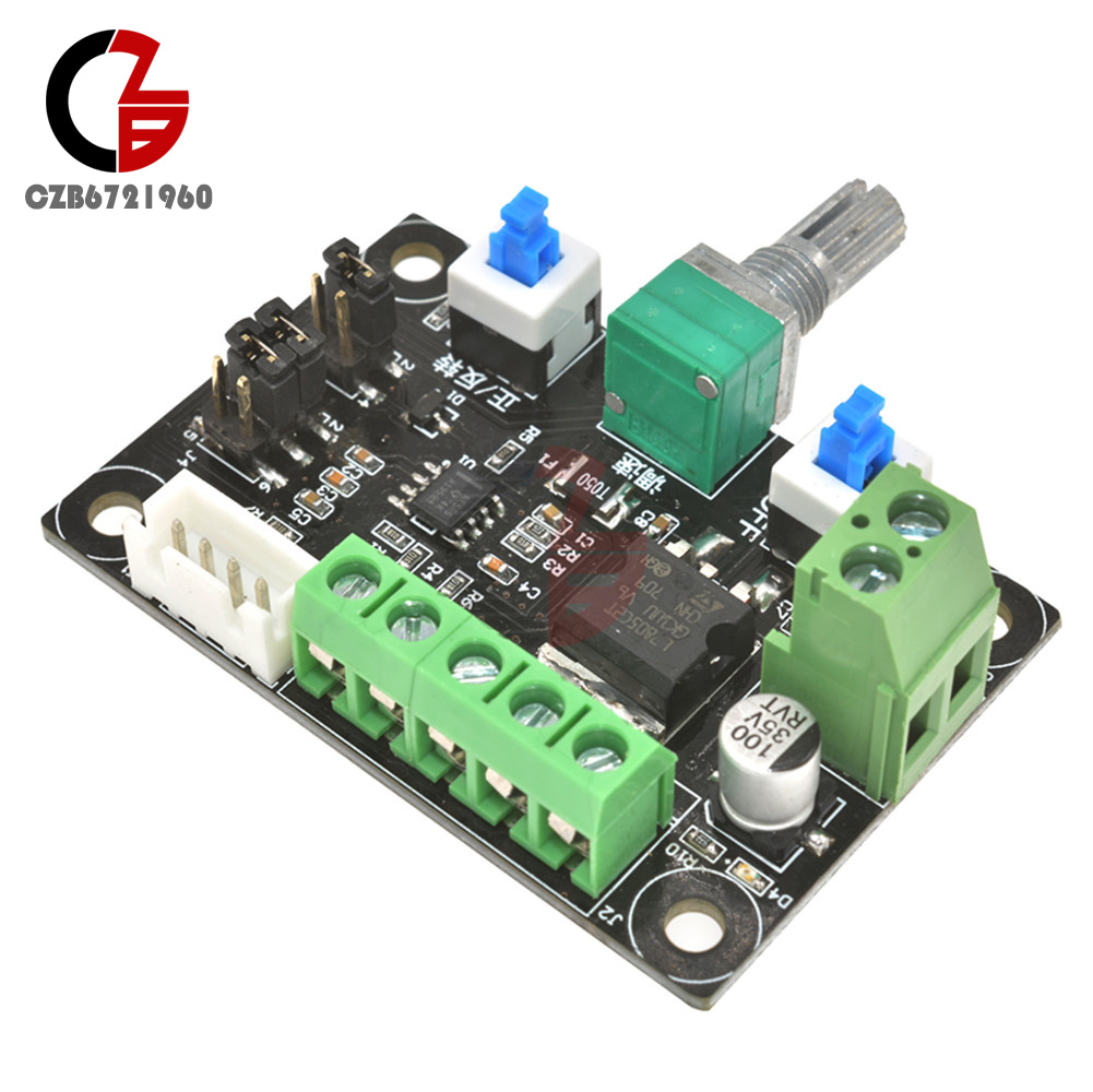
1, this module is a pulse generation module, supply the control signal to stepper driver.
To control the stepper motor, it must be equipped with a drive.
2, this simple controller + stepper motor + stepper motor + DC power supply can be composed of a simple set of control platform.
3, the controller has high 5.4k-160khz, middle 540-16.6khz, low 80-2.4khz total of 3 kinds of low frequency signal can be used to select the jumper.
4, can produce pulse signal, can also produce PWM signal, can choose the jumper.
5, the frequency of measurement: PUL and common cathode end.
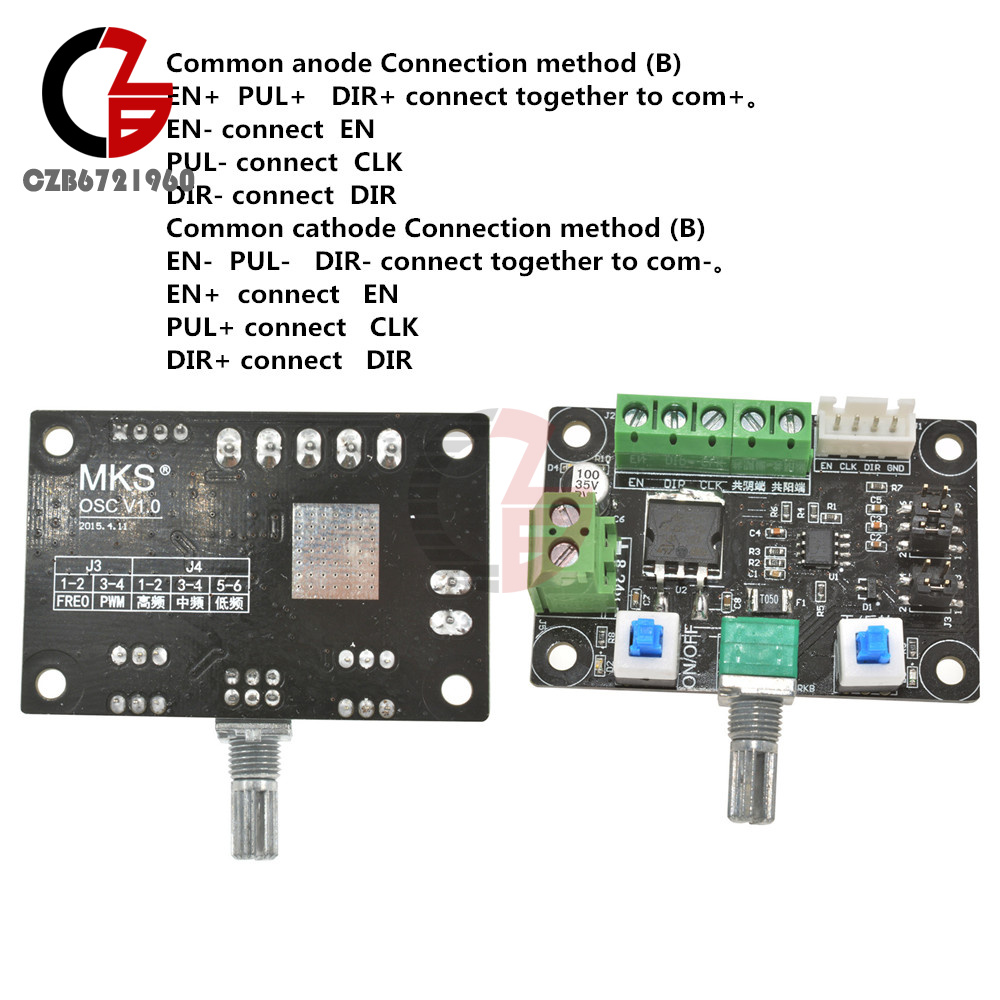
Different stepper driver may mark different name
EN=ENA=FREE Enable
PUL=PULS=CLK Pulse
DIR=CW=CWW Direction
Common anode Connection method (B)
EN+ PUL+ DIR+ connect together to com+。
EN- connect EN
PUL- connect CLK
DIR- connect DIR
Common cathode Connection method (B)
EN- PUL- DIR- connect together to com-。
EN+ connect EN
PUL+ connect CLK
DIR+ connect DIR
Package Included:1x Control Signal Generator Modul
First, the module description:
Frequency is divided into three ranges:
Frequency display example:
"100" indicates that the PWM output pulse of 100Hz;
"54.1" indicates that the PWM output pulse of 54.1KHz;
"1.2.4." Indicates that the PWM pulse output 124KHz
Duty Cycle in the range: 0 to 100;
Three frequencies duty cycle is the same, all the parameters non-volatile.
Second, the module parameters:
Third, the parameter settings:
Module has three buttons [Set], [Up], [Down];
Fourth, the scope:
Fifth, the serial control
Baud rate: 9600 bps
Data bits: 8
Stop bits: 1
Parity bit: none
Flow control: none
1, set the PWM frequency
"S1FXXXT": setting PWM1 frequency of XXX HZ (001 ~ 999)
"S1FXX.XT": set the frequency of PWM1 XX.X KHZ (00.1 ~ 99.9)
"S1F: X.X.X.T": setting PWM1 frequency of XXX KHZ (0.0.1 ~ 1.5.0..)
'S1': PWM1
'S2': PWM2
'D': Duty Cycle
'T' is the end flag
"S1DXXXT": setting PWM1 duty cycle XXX; (001 ~ 100)
"S2DXXXT": set PWM2 duty cycle XXX; (001 ~ 100)
Setting successful return: DOWN;
Setting failback: FALL.
NO Retail Box. Packed Safely in Bubble Bag.
Package Included:
1 x 2 way Independent PWM Generator
Features:
Easy to use and connect the wire, good performance.
Knob operation, immediately after adjusting the response output, no delay.
The power port has polarity protection, will not damage the components with power reverse.
Power supply voltage: DC 12V or 24V(tolerance ±25%), total power<1W.
Output load impedance range: 0-350 ohms(DC12V); 0-800 ohms(DC 24V).
The test output is normal, you can use a multimeter shorted "4-20mA output" terminal.
Can be used for signal sources, valve adjustment, output meter test, the light emitting diode test, analog transmitter.
Specifications:
Power Supply: DC 12V or 24V
Current: 4-20mA
Total Power: <1W
Output Load Impedance: 0-350 ohms(DC12V); 0-800 ohms(DC 24V)
PCB Board Size: 50 * 50mm / 1.97 * 1.97in
Product Weight: 38g / 1.37oz
Package List:1 * 4-20mA Signal Generator Module

Features:
These are all the parts, it need your own welding and installatio
Voltage Supply: 9-12V DC Input
Waveforms: Square, Sine & Triangle
Impedance: 600 Ohm + 10%
Frequency: 1Hz - 1MHz
SINE WAVE
Amplitude: 0 - 3V at 9V DC input
Distortion: Less than 1% (at 1kHz)
Flatness: +0.05dB 1Hz - 100kHz
SQUARE WAVE
Amplitude: 8V (no load) at 9V DC input
Rise Time: Less than 50ns (at 1kHz)
Fall Time: Less than 30ns (at 1kHz)
Symmetry: Less than 5% (at 1kHz)
TRIANGLE WAVE
Amplitude: 0 - 3V at 9V DC input
Linearity: Less than 1% (up to 100kHz) 10mA
2. The Function Generator component parameter table
|
Note |
label |
type |
parameters |
|
R1 |
resistor |
1K |
Regardless of the polarity |
|
R2 |
Adjustable resistance |
B503=50K |
(by screen printing layer) |
|
R3, R5,R6 |
resistor |
5.1K |
Regardless of the polarity |
|
R4 |
resistor |
330 |
Regardless of the polarity |
|
R7 |
Adjustable resistance |
B503=50K |
(by screen printing layer) |
|
R8 |
Adjustable resistance |
B104=100K |
(by screen printing layer) |
|
C1, |
Electrolytic capacitor |
100UF |
The positive short feet negative long feet |
|
C2 |
non-polar capacitors |
104 |
Regardless of the polarity |
|
C3,C4 |
Electrolytic capacitor |
10UF |
The positive short feet negative long feet |
|
C5 |
non-polar capacitors |
105 |
Regardless of the polarity |
|
C6 |
non-polar capacitors |
473 |
Regardless of the polarity |
|
C7 |
non-polar capacitors |
222 |
Regardless of the polarity |
|
C8 |
non-polar capacitors |
101 |
Regardless of the polarity |
|
U1 |
IC |
XR2206 |
(by screen printing layer) |
|
JK1 |
DC POWER |
|
(by screen printing layer) |
|
J1 |
2PIN Jumper cap |
XM2.54 |
Regardless of the polarity |
|
J2 |
2PIN Jumper cap |
XM2.54 |
Regardless of the polarity |
|
P1 |
Signal wire terminal |
|
(by screen printing layer) |
|
J3 |
2*5P Jumper cap |
|
|
3.The welding installation considerations, follow these steps:
1. The components are welding the front board, from low to high principles, namely the first low welding components, such as, capacitor, resistor, diode, etc.
2.Welding IC socket, terminal blocks, finally power socket, adjustable potentiometer.
3.The back with a diagonal cutting pliers to cut short the pins as far as possible
4.Debugging steps:
1.After completion of welding on IC, XR2206, pay attention to the direction of IC, insert the might damage the chip!
2. check the IC whether against, such as anti please timely correction.
3. Insert the power supply, power supply for 5.5 * 2.1 port, inside outside is negative polarity. For 9-12 v power supply voltage. The waveform may not be stable for more than 12 v
5.Using the step:
1. J1 jumper cap plug in, SIN/TRI blue terminals output sine wave (note J1, J2 can only insert one of)
2. J2 jumper cap plug in, SIN/TRI blue terminals output triangular wave (note J1, J2 can only insert one of)
3. SQU blue terminals output pulse
4. AMP : Sine wave, triangle wave amplitude adjustment
5. FINE : Frequency fine adjustment
6. Coarse : Frequency of coarse adjustment
7.Schematic diagram of Function Generator
Package Included:
1 x XR2206 Function Generator DIY Kit Sine, Triangle, Square Output 1HZ-1MHZ +CASE

Feature:
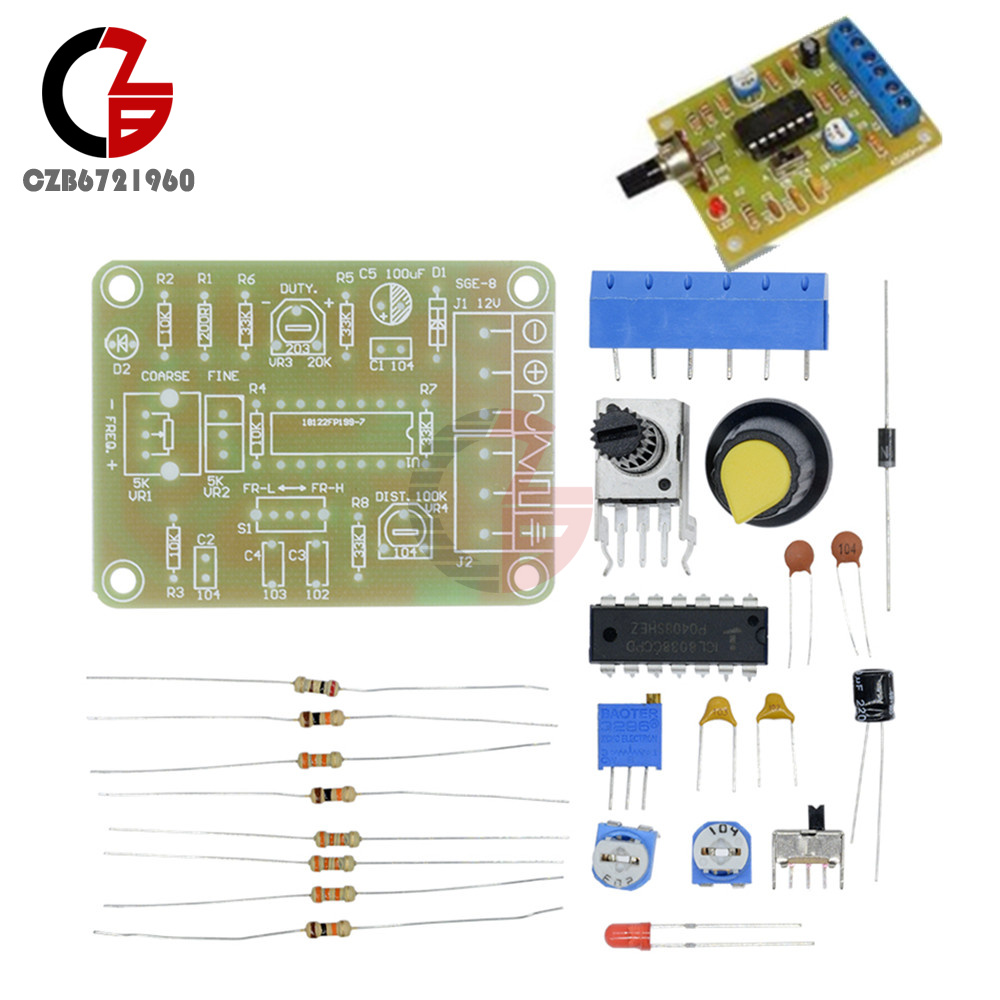
With excellent performance ASIC chip function generator ICL8038, add a small amount of resistive and capacitive components, can produce sine, triangle and square wave, and the frequency of the signal, duty cycle, adjustable distortion sine wave.
Notice:
Requires a certain DIY ability, you need to weld the kit yourself:)
Description:
ICL8038 pin functions:
1 foot, 12 foot: sine waveform adjusting terminal;
2 foot: sine wave output;
3 foot: triangle wave output;
4 foot, 5 foot: the frequency and duty cycle (or waveform asymmetry) adjustment;
6 foot: V +, the positive power supply;
7 foot: offset; 8 foot: frequency adjustment input terminal;
9 foot: square wave output.
This is an open collector output terminal, work should take a load resistor to the corresponding positive power supply terminal from the pin, to get a TTL-compatible square-wave output, the load resistance must be connected to + 5V power supply;
10 foot: timing capacitor terminal;
11 foot: V-, negative power supply terminal or the ground. Use positive and negative power supply, 11 feet to the negative supply, the output waveform are symmetrical with respect to 0V; use a single positive power supply, 11 feet grounded, the output waveform is unipolar, uniform voltage is + VCC / 2;
13 feet, 14 Feet: Empty foot.
The kits are designed for a frequency range is 50-5KHz, two bands with a switch S to switch, RP1 is the frequency adjustment, RP2 is the duty cycle adjustment, RP3 is a sine wave distortion adjustment. Circuit uses 12V single power supply, input from the X1; X2, X3 is a waveform output side, you can use oscilloscope to observe three output waveforms.
Model: ICL8038
Input 12V DC
Frequency range 50-5KHz,
Size:6cm*4.5cm*0.2cm
Package Included:
1 set function signal generator module and electronic kit
1, this module is a pulse generation module, supply the control signal to stepper driver.
To control the stepper motor, it must be equipped with a drive.
2, this simple controller + stepper motor + stepper motor + DC power supply can be composed of a simple set of control platform.
3, the controller has high 5.4k-160khz, middle 540-16.6khz, low 80-2.4khz total of 3 kinds of low frequency signal can be used to select the jumper.
4, can produce pulse signal, can also produce PWM signal, can choose the jumper.
5, the frequency of measurement: PUL and common cathode end.
Different stepper driver may mark different name
EN=ENA=FREE Enable
PUL=PULS=CLK Pulse
DIR=CW=CWW Direction
Common anode Connection method (B)
EN+ PUL+ DIR+ connect together to com+。
EN- connect EN
PUL- connect CLK
DIR- connect DIR
Common cathode Connection method (B)
EN- PUL- DIR- connect together to com-。
EN+ connect EN
PUL+ connect CLK
DIR+ connect DIR
Package Included:1x Control Signal Generator Modul
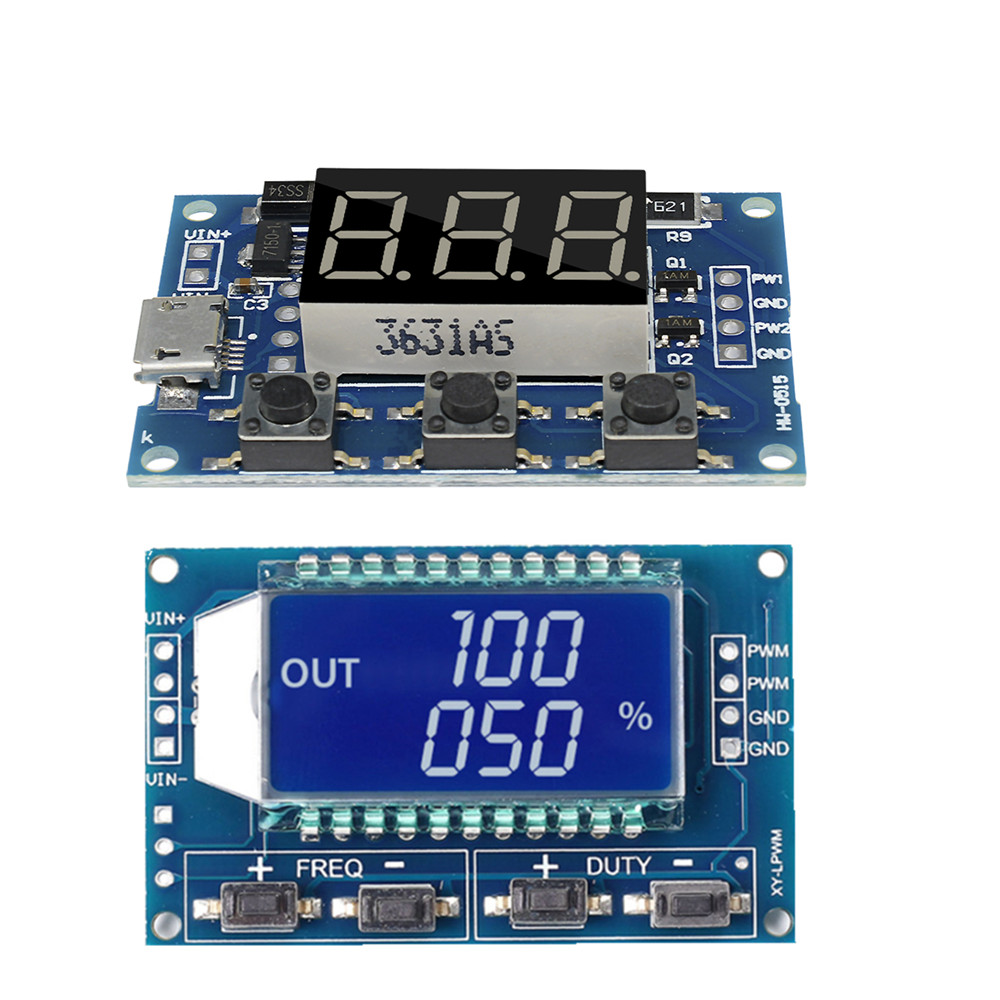
First, the module description:
Frequency is divided into three ranges:
Frequency display example:
"100" indicates that the PWM output pulse of 100Hz;
"54.1" indicates that the PWM output pulse of 54.1KHz;
"1.2.4." Indicates that the PWM pulse output 124KHz
Duty Cycle in the range: 0 to 100;
Three frequencies duty cycle is the same, all the parameters non-volatile.
Second, the module parameters:
Third, the parameter settings:
Module has three buttons [Set], [Up], [Down];
Fourth, the scope:
Fifth, the serial control
Baud rate: 9600 bps
Data bits: 8
Stop bits: 1
Parity bit: none
Flow control: none
1, set the PWM frequency
"S1FXXXT": setting PWM1 frequency of XXX HZ (001 ~ 999)
"S1FXX.XT": set the frequency of PWM1 XX.X KHZ (00.1 ~ 99.9)
"S1F: X.X.X.T": setting PWM1 frequency of XXX KHZ (0.0.1 ~ 1.5.0..)
'S1': PWM1
'S2': PWM2
'D': Duty Cycle
'T' is the end flag
"S1DXXXT": setting PWM1 duty cycle XXX; (001 ~ 100)
"S2DXXXT": set PWM2 duty cycle XXX; (001 ~ 100)
Setting successful return: DOWN;
Setting failback: FALL.
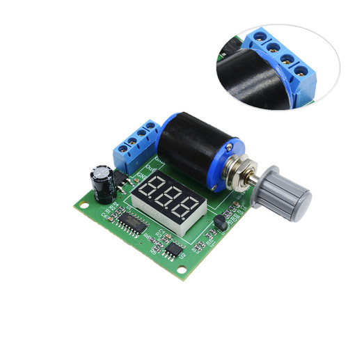
NO Retail Box. Packed Safely in Bubble Bag.
Package Included:
1 x 2 way Independent PWM Generator
Features:
Easy to use and connect the wire, good performance.
Knob operation, immediately after adjusting the response output, no delay.
The power port has polarity protection, will not damage the components with power reverse.
Power supply voltage: DC 12V or 24V(tolerance ±25%), total power<1W.
Output load impedance range: 0-350 ohms(DC12V); 0-800 ohms(DC 24V).
The test output is normal, you can use a multimeter shorted "4-20mA output" terminal.
Can be used for signal sources, valve adjustment, output meter test, the light emitting diode test, analog transmitter.
Specifications:
Power Supply: DC 12V or 24V
Current: 4-20mA
Total Power: <1W
Output Load Impedance: 0-350 ohms(DC12V); 0-800 ohms(DC 24V)
PCB Board Size: 50 * 50mm / 1.97 * 1.97in
Product Weight: 38g / 1.37oz
Package List:1 * 4-20mA Signal Generator Module
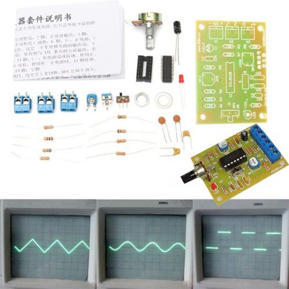
Features:
These are all the parts, it need your own welding and installatio
Voltage Supply: 9-12V DC Input
Waveforms: Square, Sine & Triangle
Impedance: 600 Ohm + 10%
Frequency: 1Hz - 1MHz
SINE WAVE
Amplitude: 0 - 3V at 9V DC input
Distortion: Less than 1% (at 1kHz)
Flatness: +0.05dB 1Hz - 100kHz
SQUARE WAVE
Amplitude: 8V (no load) at 9V DC input
Rise Time: Less than 50ns (at 1kHz)
Fall Time: Less than 30ns (at 1kHz)
Symmetry: Less than 5% (at 1kHz)
TRIANGLE WAVE
Amplitude: 0 - 3V at 9V DC input
Linearity: Less than 1% (up to 100kHz) 10mA
2. The Function Generator component parameter table
|
Note |
label |
type |
parameters |
|
R1 |
resistor |
1K |
Regardless of the polarity |
|
R2 |
Adjustable resistance |
B503=50K |
(by screen printing layer) |
|
R3, R5,R6 |
resistor |
5.1K |
Regardless of the polarity |
|
R4 |
resistor |
330 |
Regardless of the polarity |
|
R7 |
Adjustable resistance |
B503=50K |
(by screen printing layer) |
|
R8 |
Adjustable resistance |
B104=100K |
(by screen printing layer) |
|
C1, |
Electrolytic capacitor |
100UF |
The positive short feet negative long feet |
|
C2 |
non-polar capacitors |
104 |
Regardless of the polarity |
|
C3,C4 |
Electrolytic capacitor |
10UF |
The positive short feet negative long feet |
|
C5 |
non-polar capacitors |
105 |
Regardless of the polarity |
|
C6 |
non-polar capacitors |
473 |
Regardless of the polarity |
|
C7 |
non-polar capacitors |
222 |
Regardless of the polarity |
|
C8 |
non-polar capacitors |
101 |
Regardless of the polarity |
|
U1 |
IC |
XR2206 |
(by screen printing layer) |
|
JK1 |
DC POWER |
|
(by screen printing layer) |
|
J1 |
2PIN Jumper cap |
XM2.54 |
Regardless of the polarity |
|
J2 |
2PIN Jumper cap |
XM2.54 |
Regardless of the polarity |
|
P1 |
Signal wire terminal |
|
(by screen printing layer) |
|
J3 |
2*5P Jumper cap |
|
|
3.The welding installation considerations, follow these steps:
1. The components are welding the front board, from low to high principles, namely the first low welding components, such as, capacitor, resistor, diode, etc.
2.Welding IC socket, terminal blocks, finally power socket, adjustable potentiometer.
3.The back with a diagonal cutting pliers to cut short the pins as far as possible
4.Debugging steps:
1.After completion of welding on IC, XR2206, pay attention to the direction of IC, insert the might damage the chip!
2. check the IC whether against, such as anti please timely correction.
3. Insert the power supply, power supply for 5.5 * 2.1 port, inside outside is negative polarity. For 9-12 v power supply voltage. The waveform may not be stable for more than 12 v
5.Using the step:
1. J1 jumper cap plug in, SIN/TRI blue terminals output sine wave (note J1, J2 can only insert one of)
2. J2 jumper cap plug in, SIN/TRI blue terminals output triangular wave (note J1, J2 can only insert one of)
3. SQU blue terminals output pulse
4. AMP : Sine wave, triangle wave amplitude adjustment
5. FINE : Frequency fine adjustment
6. Coarse : Frequency of coarse adjustment
7.Schematic diagram of Function Generator
Package Included:
1 x XR2206 Function Generator DIY Kit Sine, Triangle, Square Output 1HZ-1MHZ +CASE
Feature:
With excellent performance ASIC chip function generator ICL8038, add a small amount of resistive and capacitive components, can produce sine, triangle and square wave, and the frequency of the signal, duty cycle, adjustable distortion sine wave.
Notice:
Requires a certain DIY ability, you need to weld the kit yourself:)
Description:
ICL8038 pin functions:
1 foot, 12 foot: sine waveform adjusting terminal;
2 foot: sine wave output;
3 foot: triangle wave output;
4 foot, 5 foot: the frequency and duty cycle (or waveform asymmetry) adjustment;
6 foot: V +, the positive power supply;
7 foot: offset; 8 foot: frequency adjustment input terminal;
9 foot: square wave output.
This is an open collector output terminal, work should take a load resistor to the corresponding positive power supply terminal from the pin, to get a TTL-compatible square-wave output, the load resistance must be connected to + 5V power supply;
10 foot: timing capacitor terminal;
11 foot: V-, negative power supply terminal or the ground. Use positive and negative power supply, 11 feet to the negative supply, the output waveform are symmetrical with respect to 0V; use a single positive power supply, 11 feet grounded, the output waveform is unipolar, uniform voltage is + VCC / 2;
13 feet, 14 Feet: Empty foot.
The kits are designed for a frequency range is 50-5KHz, two bands with a switch S to switch, RP1 is the frequency adjustment, RP2 is the duty cycle adjustment, RP3 is a sine wave distortion adjustment. Circuit uses 12V single power supply, input from the X1; X2, X3 is a waveform output side, you can use oscilloscope to observe three output waveforms.
Model: ICL8038
Input 12V DC
Frequency range 50-5KHz,
Size:6cm*4.5cm*0.2cm
Package Included:
1 set function signal generator module and electronic kit