

Built-in Bluetooth: Support for Android and IOS
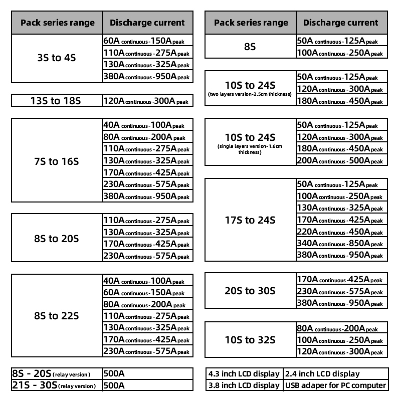
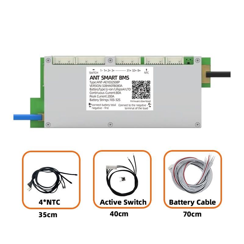
Number of detectable strings: 10-32S battery
Support cell: Li-ion, LiFePo4, LTO
Power supply: battery pack self-powered, 24-150V DC input
Monomer voltage detection: 0-5V, error < 10mV in the whole working range, typical error value < 5mV
Single voltage drop detection: Supported
Balancing function: maximum 280mA passive balancing
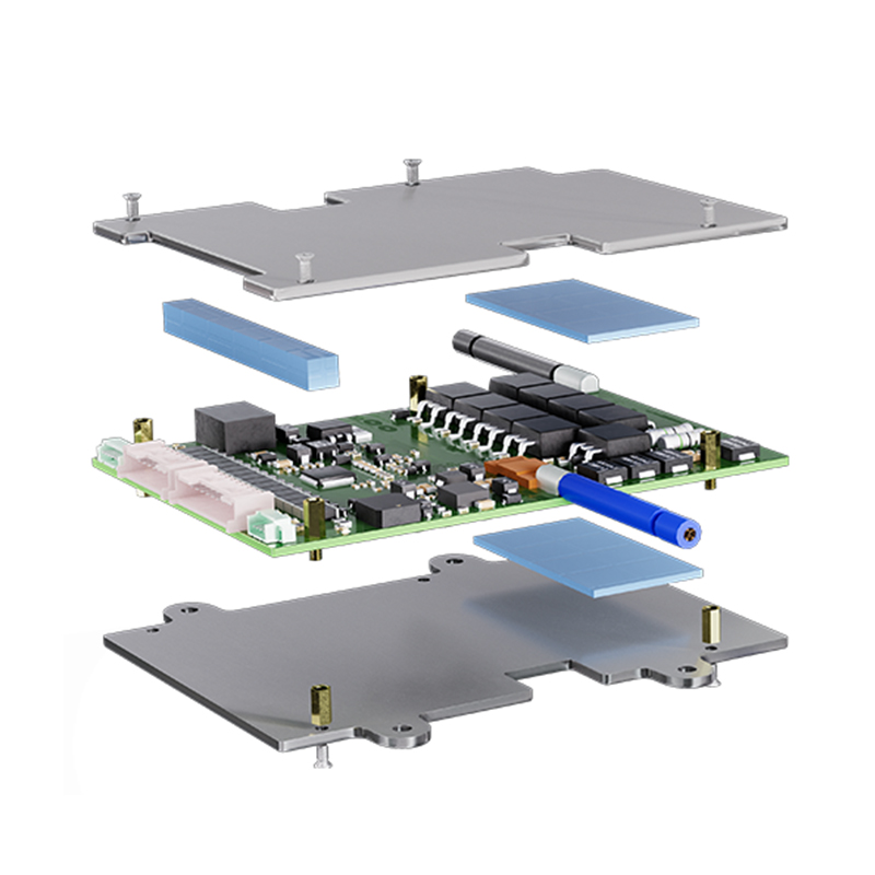
Product characteristics
Bluetooth function
APP can view parameters, set different cell types, battery string number, battery capacity and other parameters, display protection information, fault records, etc
Monomer voltage acquisition
Supports a maximum of 32S battery for real-time voltage sampling, and the total voltage is greater than 24V. Support 10S~32S of Li-ion, LiFePo4, and Lithium Titanate
Temperature acquisition
Sample cell surface temperature, ambient temperature, MOSFET temperature and equalization circuit temperature
SOC/ SOH calculation
Calculate the remaining capacity of the battery and the health information to get the working status of the battery string
MOSFET driver
Driven by MOSFET, the power loop is switched on/off
Total voltage detection
You can check whether precharge is complete and check the total battery voltage
Current detection
By detecting current, real-time current detection, short circuit protection, sleep/wake up and other functions are realized
Battery equalization
Energy dissipation balance through passive resistance can effectively maintain the battery and improve the consistency. Active balance can be achieved by setting parameters to meet the conditions
Description:
This BMS supports 10S-32S of LiPo, LiFePo4 and LTO batteries etc...
Charge current 50A
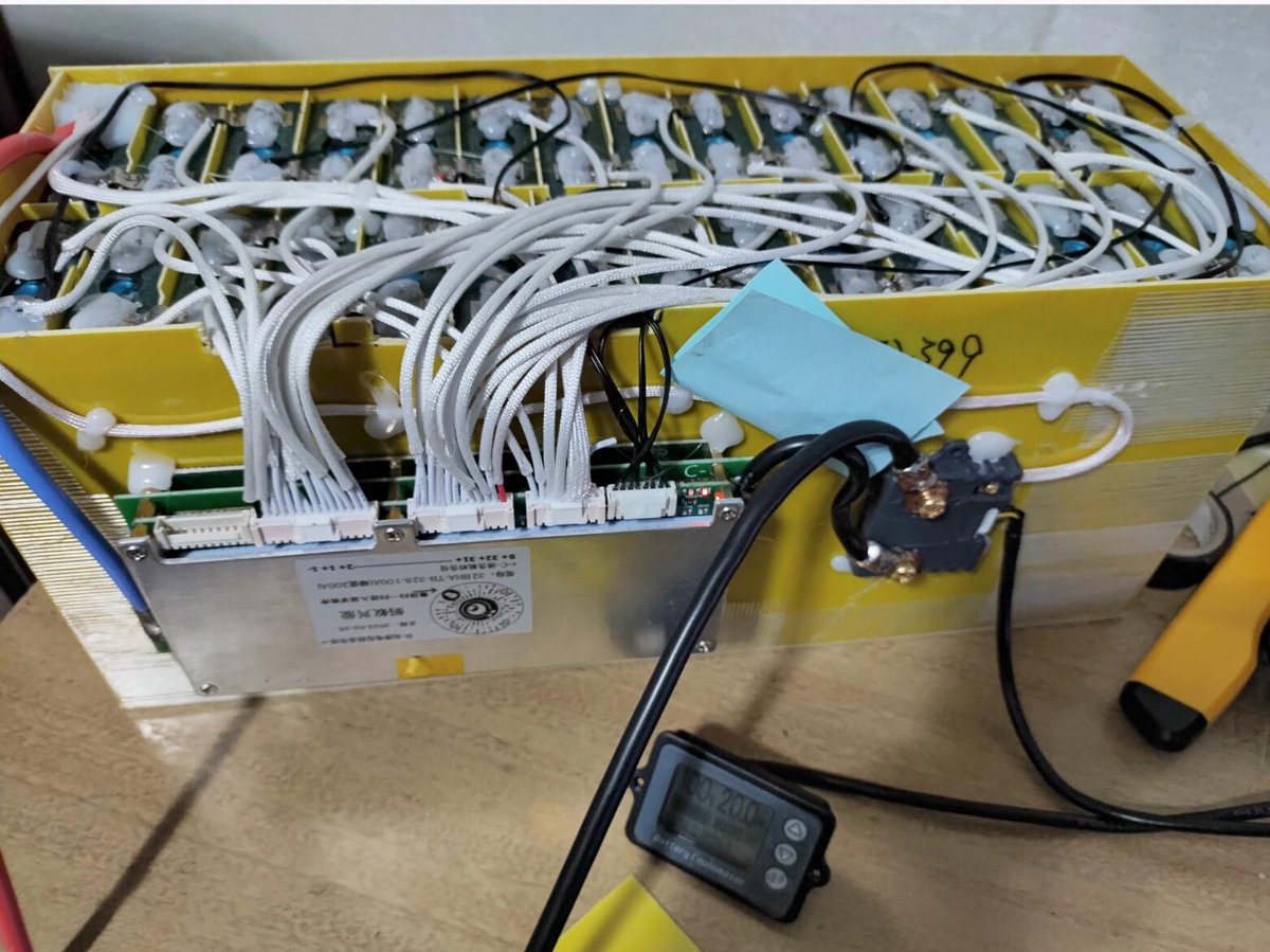
Wiring connection notice:
The cable will be connected from the first black wire on the far right to the total negative electrode of the battery pack, which is the negative electrode of the first cell of batteries.
Then start from the black wire and start from the first white wire from right to left to the first cell, second cell, third cell of the battery and so on, and connect to the positive electrode of each cell in sequence. The minimum number of cells to be connected is 10S, and the batteries of less than 32S are not left empty. After connecting, use a multimeter to measure the voltage on the plug row. There is no problem to confirm that the voltage is correct before plugging into the protection board The same wire is connected to a red wire, regardless of its color), note that the last red wire on the third and last socket is B + which supplies power to the protection board. It is connected to the cable of the last cell of batteries. That is to say, two wires need to be connected to the bms on the last positive pole of the battery. There is a hole behind the last red wire of the third socket and B + is redundant. You can leave it alone. Other instructions are the same as the 24S BMS
Package includes.
1*10S-32S ANT SMART BMS
1*Cable