Product Feature:
1. The product is made of high-quality materials with guaranteed quality
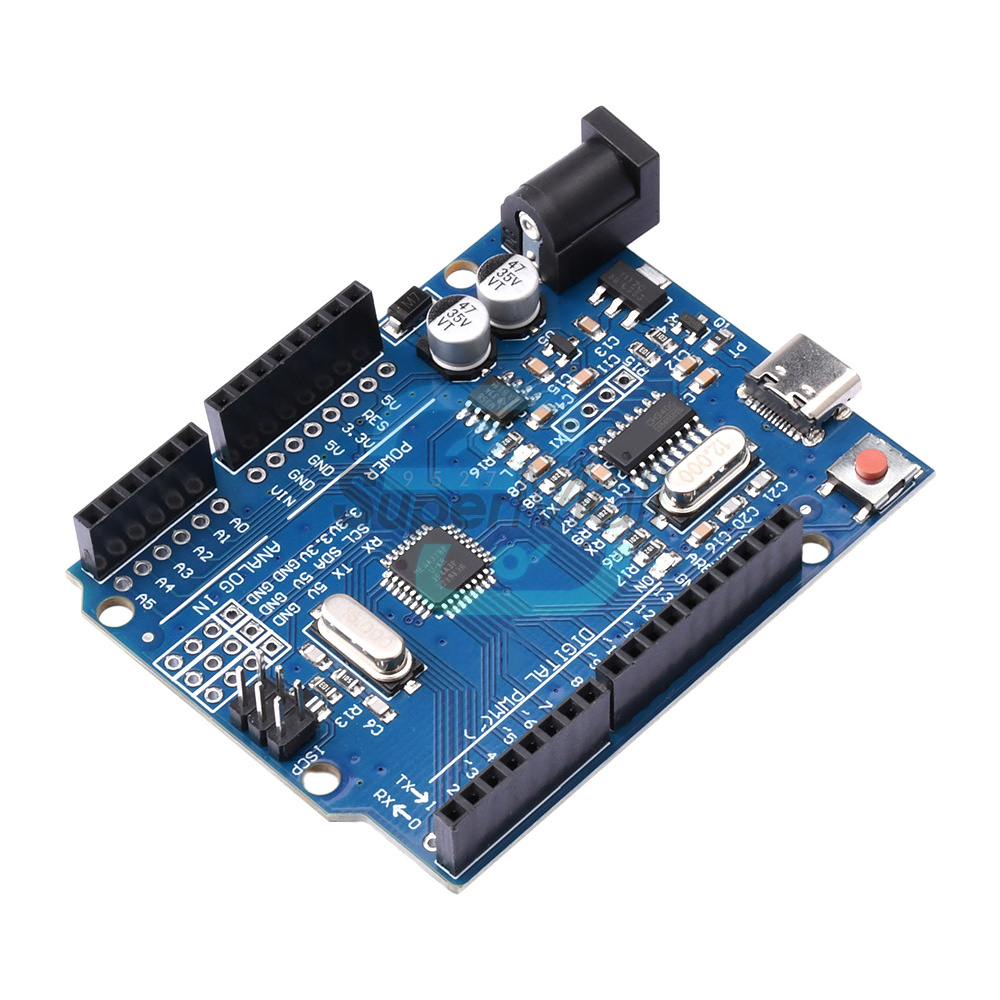
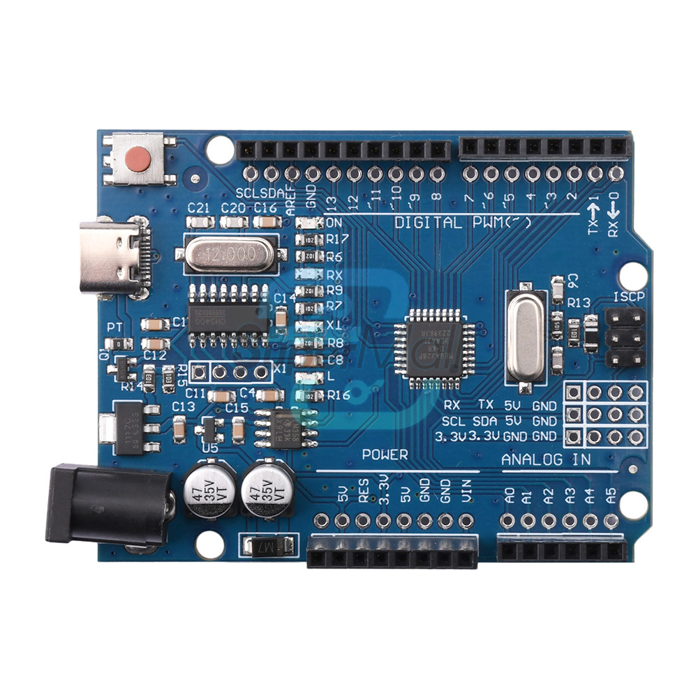
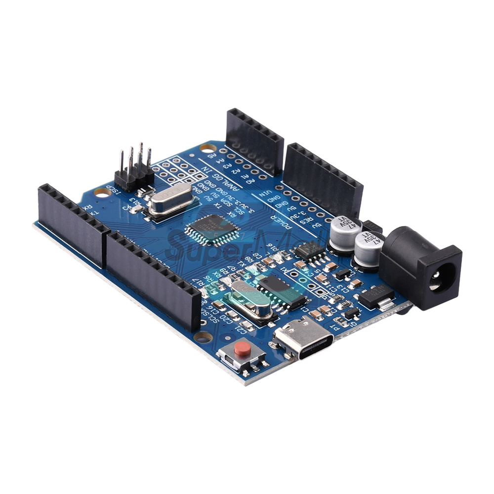
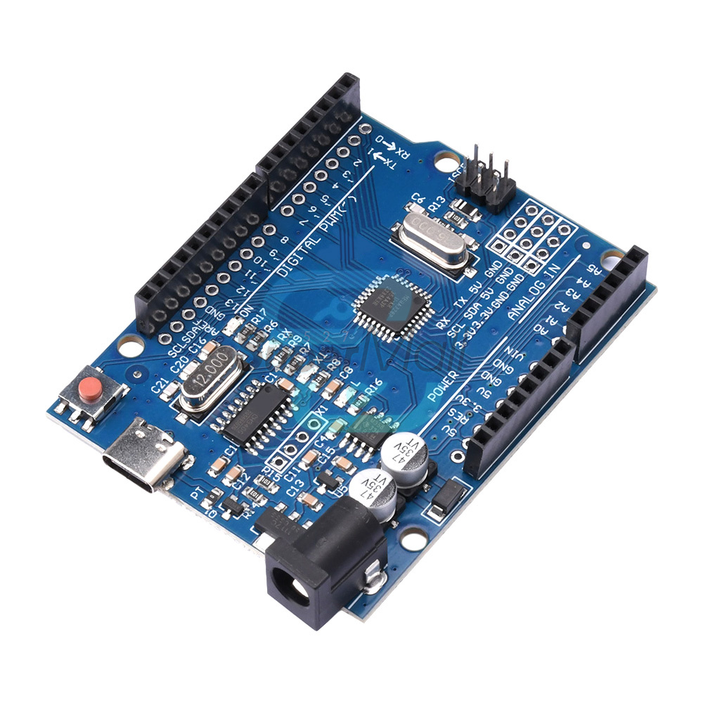
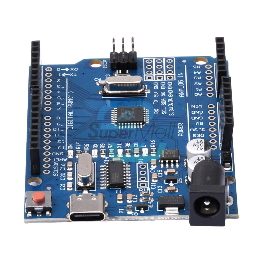
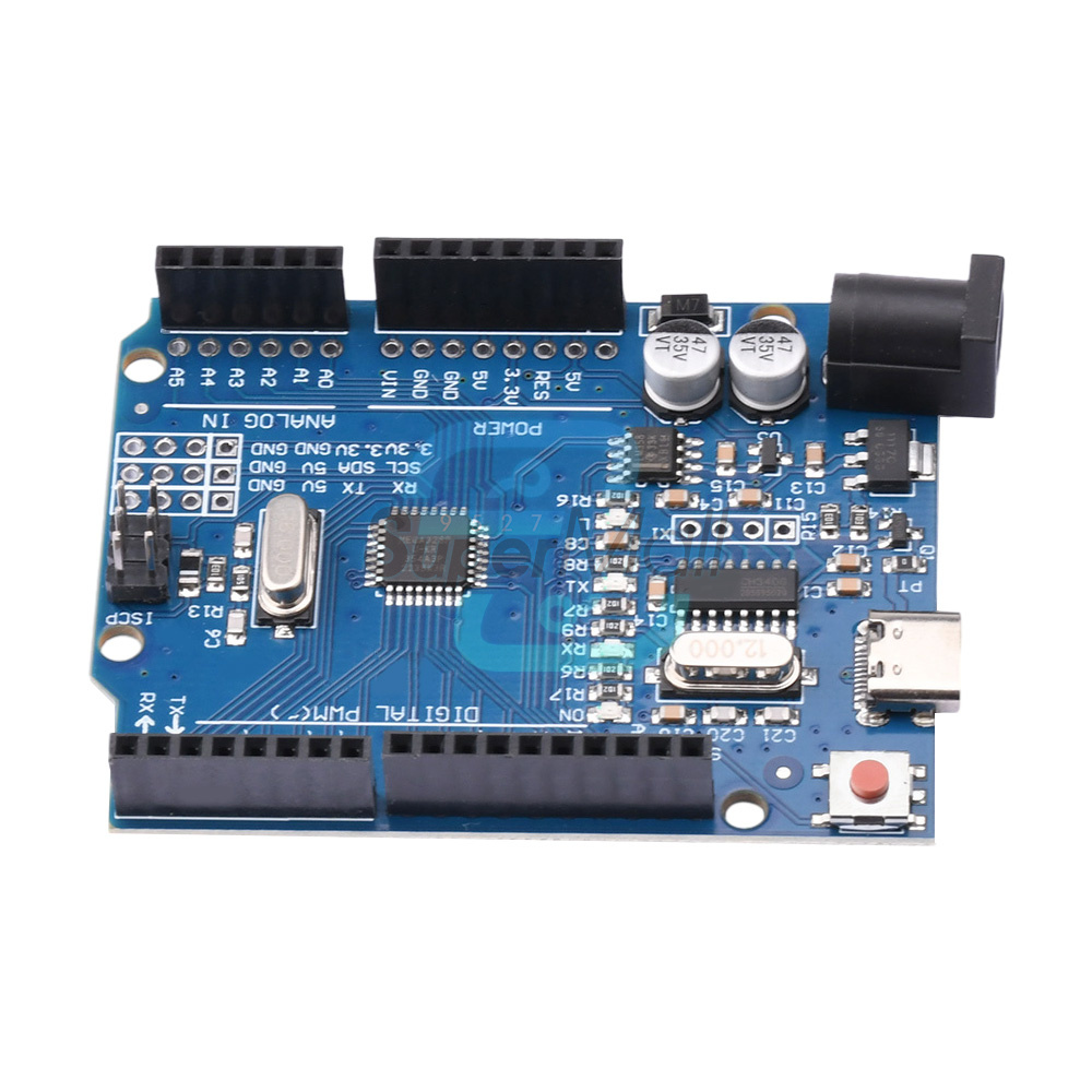
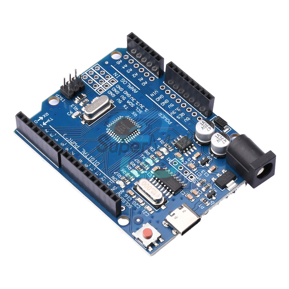
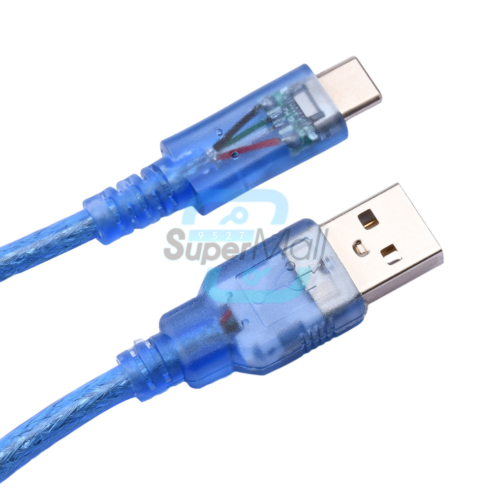
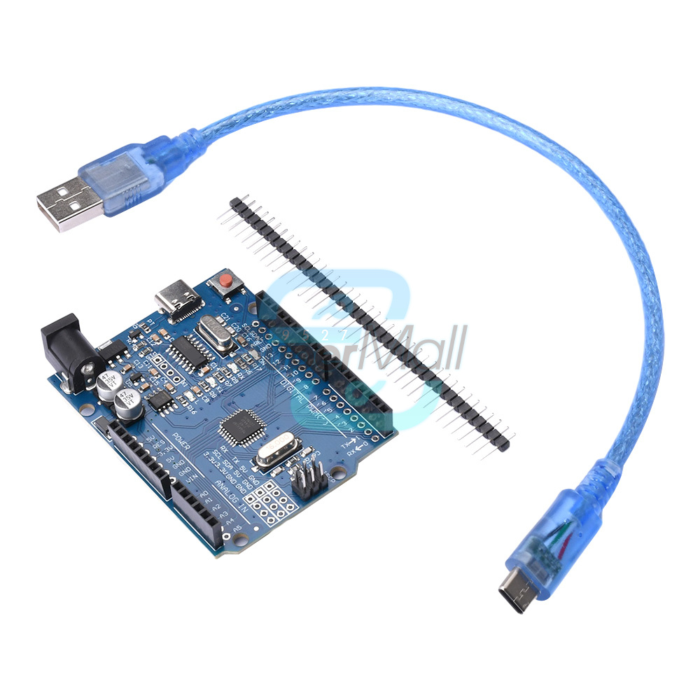
2. The product has TYPE-C USB interfaces.
3. Pin and socket design for easy use of DuPont cables
4. This version is an optimization on the original version, which can solve the problem of instability and incompatibility, ensure consistency and compatibility with the original version, and make it convenient for everyone to use
Especially in pirated 64 bit WIN7 systems, the official board cannot install drivers, and this version is very simple and convenient to install
6. You can easily use sensors to connect various electronic components (such as LED lights, buzzers, buttons, photosensitive resistors, etc.) and create various interesting works
7. Adopting a high-speed microprocessor controller (ATMEGA328P), the development of the user interface and environment are very simple, easy to understand, and very suitable for beginners to learn
Product Overview:
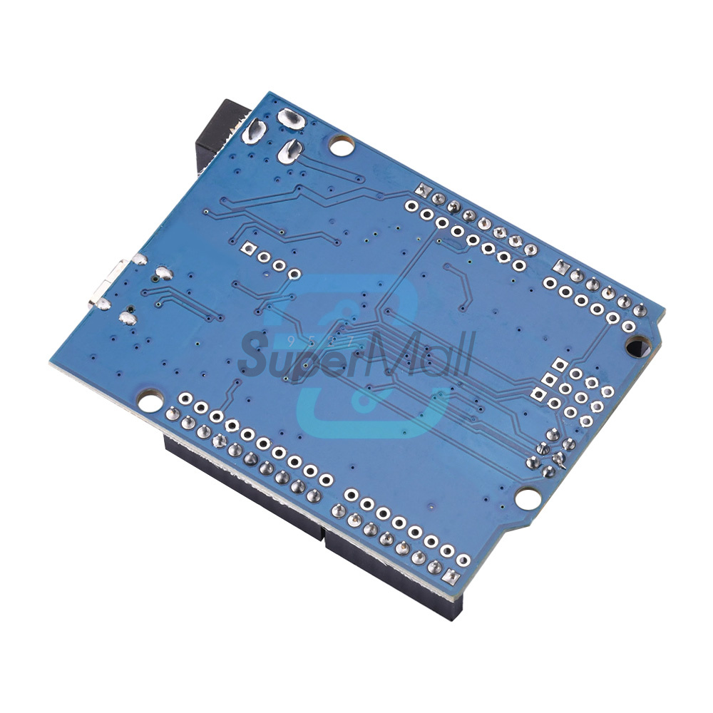
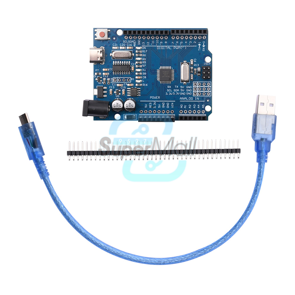
The R3 development board is a microcontroller board based on ATmega328P. It has 14 digital input/output pins (6 of which can be used as PWM outputs), 6 analog inputs, 16MHz crystal clock, USB connection, power socket, IIC, SPI interface, and reset button. Simply connect the computer through a USB data cable to provide power, program download, and data communication.
Parameters:
USB power supply voltage: 5V
DC port power supply voltage: 7V-12V
Main controller model: ATMEGA328P
USB to serial port chip model: CH340G
Digital 10 ports: 14 (of which 6 can be used as PWM ports)
External power limit current 1A
I0 port limit high current 40mA
Analog input pins: 6 (2 of which can be used as 12C interfaces)
Flash storage capacity: 32KB
(2KB has been used as BootLoader space)
SRAM: 2KB
EEPROM: 1KB
Clock frequency: 16MHZ
Pin introduction:
Power pin: The development board can provide 3.3V and 5V voltage outputs, and the Vin pin can be used to power the development board from an external power source. Analog In pin: Analog input pin, the development board can read external analog signals, and A0~A5 are analog input pins.
Digital pin: R3 has 14 digital I/O pins, of which 6 can be used for PWM (pulse width modulation) output. Digital pins are used to read logical values (0 or 1), or as digital output pins to drive external modules. Pins marked with "~" can generate PWM.
TX and RX pins: The two pins labeled TX (transmit) and RX (receive) are used for serial communication. The LED lights labeled TX and RX are connected to the corresponding pins and will flash at different speeds during serial communication.
Pin 13: Mark the 13th pin on the development board, connect the onboard LED light, and control the LED light to turn on or off by controlling pin 13. Generally, the onboard light on the development board will flash, which can assist in detecting whether the development board is functioning properly.
Usage:
Download IDE
Insert the development board and install the driver in the IDE to select the board
Select the COM port, which can be queried in the Device Manager
It's best to choose the built-in routine program first and burn it in
Shipping list:
Module X1
Pin X1
Data cable X1 (depend on your choice)