Classification of hot melt drill bits(Fdrill)
1.According to the requirements of the workpiece surface, Fdrill hot melt drill is divided into "standard type (frictiondrill guichenoti type frictiondrill)" and "flat type (frictiondrill row flat frictiondrill)":
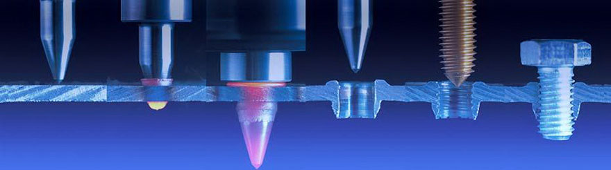
- standard type frictiondrill (guichenoti type frictiondrill): frictiondrill penetrate the workpiece while drawing the bushing to form a convex ring. The surface of the boss, suitable for thread sealing or nut washer
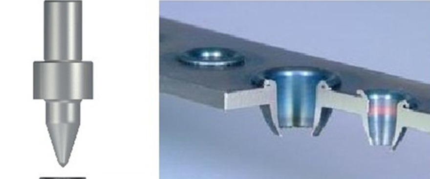
- Flat type frictiondrill (designated flat frictiondrill): the middle part of the drill grinding step melt cutter blade, and the hot melt drilling liner to penetrate the workpiece drawing to form a convex surface of the workpiece (ring cut milling and chamfer), make the surface smooth

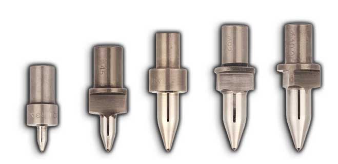
2.According to the thickness of the workpiece, Flowdrill is divided into short drill and long drill
- Short drill: used for thin-walled parts. Apply to penetrate workpiece thickness at 0.8mm -3mm. The part of the drill cylinder is short and the hole formed after extrusion is conical,Tapping the strength of tapping.
- Long drill: For thicker workpieces or for straight holes. Applicable to penetrate the workpiece thickness greater than 3mm-12mm. Drill cylinder part of a longer, squeeze formed after the formation of the hole longer.
Equipment and tools to be used with Flowdrill
- machine configuration: general drilling, radial drilling, milling and NC / CNC machining centers are suitable for hot melt drilling, spindle motor power is sually required 1.5KW - 3.0KW,Speed 1,000RPM - 3,500RPM.
- the tool configuration:1.Fdril hot melt drill 2. Extrusion tap 3. Heat sink and chuck 4. Hot melt hot melt adhesive paste 5. Special wire tapping oil squeeze attack 6. Special wrench set
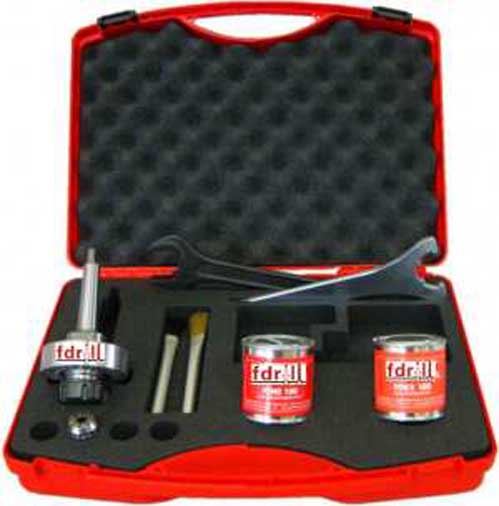
This item is not included in the list.
Manual feed Recommended operating procedure
- According to the product processing needs to correctly select the Flowdrill (aperture and type)
- Select the recommended power and speed
- Use the recommended heat sink
- Screw the collet into the heat-sink handle lock nut and insert it into the handle
- Insert the Flowdrill bit into the chuck and lock it (check and adjust the clamping force of the tool periodically)
- Connect the cooling tool holder to the drilling machine
- Fasten the work piece on the table
- Ensure the proper operating range between the workpiece and the Flowdrill (correctly set the start and end positions)
- Select the speed correctly
- Select the drilling depth correctly
- Select the recommended feed rate according to the material and thickness
- When the new drill is used for the first time, add a small amount of hot melt to the drill bit
- Both hands under the pressure of the two handles, to keep the rules of uniform feed rate, can not stop
- When the bottom of the hot melt drill bit reaches the workpiece surface, soften and quickly loosen the handle
- observe the drilling time and drill color (drill bit is correct when the Flowdrill dark red, bright red or yellow color shows Flowdrill bit overheating, speed too fast)
- Adjust the speed, feed depth and feedrate (steps 9, 10, 11). Too high: Lower the speed or increase the feed rate, or both
- Note:
First, the new drill for the first time, add a small amount of hot melt on the rotating Flowdrill; drill a good hole, add a small amount of hot melt on the rotating Flowdrill bit, keep 10 Holes.
Second, then, after drilling 2-3 holes, add a small amount of hot melt on the rotating hot melt drill.
Third, before each tapping, add a small amount of tapping oil in the rotating extrusion tap on.
safety warning:
- Always wear safety gloves and goggles during the operation of the Flowdrill;
- Do not touch directly with the hand until the workpiece has cooled down;
- Flat-type Flowdrill operation due to a chip flying out, please wear protective clothing.
The installation of the cooling tool holder and chuck
correct/wrong
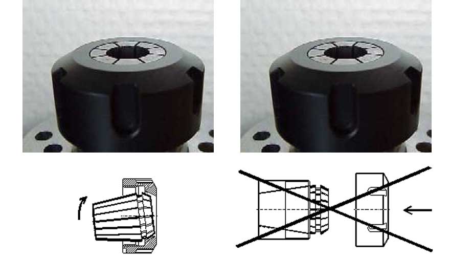
First screw the collet into the shank nut, and then turn the nut and shank /
Do not insert the chuck directly into the shank
Installation of Flowdrill
correct/wrong
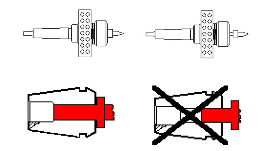
Insert the drill bit shank completely into the chuck. / Do not insert only part of the shank into the chuck
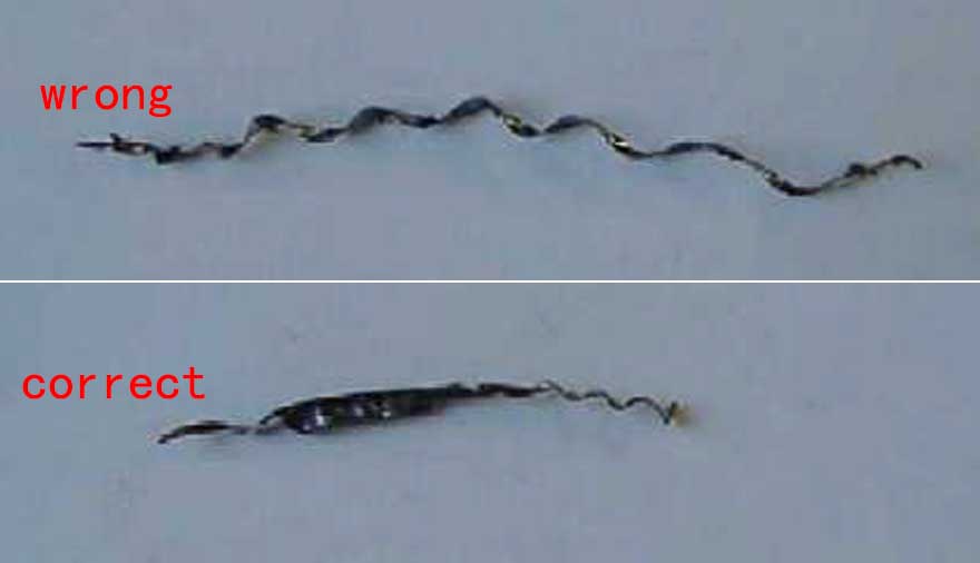
Note: The operation of the flat Flowdrill
- Will produce a small drill cuttings, this drill is very hot, please wear protective clothing, others do not close!
- In the flat-type drill operation, only the beginning of cutting, the moment to accelerate the feed. Instantly accelerating the feed will greatly extend the tool life.
- By observing the length and shape of the cuttings, the accuracy of the operation can be determined.(Drilling debris is long and thin, wrong;Drilling debris short and thick, correct.)
Precautions for use of Flowdrill
- Flowdrill is made of very brittle carbide, easy to break, the use must be careful not to fall to the ground, do not use any items percussion drill.The edge of the flat Flowdrill is fragile, please pay attention to protection.
- Workpiece material: hot melt drill for a variety of metal materials, such as steel (tensile strength less than 700N / mm2), the workpiece diameter of 1.8-32mm, wall thickness of 0.5 ~ 12.5mm,Stainless steel, titanium, aluminum, copper, copper, brass (Zn content less than 40%), aluminum alloy (si content less than 0.5%). If the material is thicker and harder, the Flowdrill is used The shorter the life.
- on the drilling requirements: as long as the power and speed to meet the requirements of most of the better quality of the drill, milling machines and CNC machining centers are suitable for hot melt drilling work. Compared with the traditional processing technology, hot melt drilling processing requires a higher speed, aperture size, material thickness and the material itself is different affect the speed of the determination.
- Workpiece material to be processed must be clamped.
- Flowdrill holder and chuck, if there is no dedicated radiator, you can use compressed air cooling.
 Flowdrill paste: hot melt drill at work, and instantly produce more than 600 °C temperature, a special hot melt paste can extend the life of the drill Life, to improve the quality of the inner surface of the cylinder, resulting in a clean and satisfactory edge shape. You can manually apply hot melt, you can also automatically spray lubricants. Do not Lubrication of the Flowdrill with conventional coolant may result in fracture of the Flowdrill. Because the general oil can not reach the high temperature, must use specially develops the hot melt drill to be special-purpose Of Flowdrill paste. Do not add lubricant to the workpiece material, the hot-melt paste must be applied to the Flowdrill work site. Flowdrill paste: hot melt drill at work, and instantly produce more than 600 °C temperature, a special hot melt paste can extend the life of the drill Life, to improve the quality of the inner surface of the cylinder, resulting in a clean and satisfactory edge shape. You can manually apply hot melt, you can also automatically spray lubricants. Do not Lubrication of the Flowdrill with conventional coolant may result in fracture of the Flowdrill. Because the general oil can not reach the high temperature, must use specially develops the hot melt drill to be special-purpose Of Flowdrill paste. Do not add lubricant to the workpiece material, the hot-melt paste must be applied to the Flowdrill work site.- Do not stay at the bottom of the hole. Once the hole drilled, it is necessary to immediately remove the Flowdrill. Otherwise, when the hole cools down, it may cause the bit to be jammed Live or break.
- Drilling spindle instability can cause drill damage, do not drill the incomplete hole, because the hole has been contracted. The same hole for some reason not completed, can not be re-drilling, must be abandoned.
- Do not use long drills to drill thin materials. Processing of very thin material is recommended standard short drilling or flat short drilling, so you can get a better processing results.
 Guide hole (prefabricated hole, bottom hole) Guide hole (prefabricated hole, bottom hole)
In the processing of very thick materials or large-diameter Flowdrill, it is recommended to drill pre-hole. It is necessary to drill a conical pre-hole to maximize the contact area of the drill bit. Prefabricated holes can shorten the drilling time, can control the temperature when drilling, reducing the formation of high temperature. By pre-drilling a small pre-hole can reduce the axial force can also reduce the height of the cylinder can also be at the end of the cylinder to produce a smooth edge, but also to avoid the thin-walled (less than 1.5 mm) bending of the workpiece Deformation. Drilling point Flowdrill tip (with cutting edge on the head), recommended for processing the surface coating of the workpiece material. Because this type of drill tip helps to remove any coating covering the surface of the workpiece at the beginning of the drilling process, such as painting, galvanizing, or any other obstructive drilling. This cutting edge is also used to help prevent deformation of thin-walled workpieces that may occur under downward pressure from the drill bit. With the cutting edge of the drill bit so that drilling becomes very easy, due to the presence of cutting edge, drilling may be appropriate to reduce the axial force, suitable for: the workpiece thickness is thin and easy to bend when drilling; Small material. Drilling point Flowdrill tip (with cutting edge on the head), recommended for processing the surface coating of the workpiece material. Because this type of drill tip helps to remove any coating covering the surface of the workpiece at the beginning of the drilling process, such as painting, galvanizing, or any other obstructive drilling. This cutting edge is also used to help prevent deformation of thin-walled workpieces that may occur under downward pressure from the drill bit. With the cutting edge of the drill bit so that drilling becomes very easy, due to the presence of cutting edge, drilling may be appropriate to reduce the axial force, suitable for: the workpiece thickness is thin and easy to bend when drilling; Small material.- Do not stop operation at any point in the drilling process.
- Make sure that the direction of rotation of the hot-melt drill is correct.
- When tapping, use tapping oil. An extrusion tap is recommended, which is not formed by cutting but by extrusion, and therefore has a high tensile strength and torque value. If the use of ordinary cutting taps easy to cut the liner, and the bottom hole and the required depth of different hot-melt drill needs to be customized.
Factors Affecting the Service Life of Flowdrill
- Thermal stress (operating temperature)
Although the mechanical strength of Flowdrill bit can still be maintained at high temperatures, but the material is still sensitive to thermal stress, it must avoid rapid temperature rise or decrease. Observe the drill bit operating temperature, drill bit dark red is the best; otherwise, should adjust the speed and feed rate, if necessary, add compressed air cooling (can not use water-cooled), so that the drill bit dark red. Avoid drilling for too long and avoid the drill bit stopping at the bottom of the hole. - Physical stress
Flowdrill is made of very hard but very brittle hard alloy, easy to break. Operation should be careful not to fall on the ground, do not use a hard object to beat the drill. As far as possible, do not drill holes in the weld, to avoid radial pressure on the drill bit to ensure vertical drilling in the workpiece. - Torque stability
Hot melt drill is not resistant to shock, it can not be fast-touch materials to the tip, and stable pressure (the right feed rate) is very important. In the penetration of materials, the need to avoid the occurrence of deflection effect, the pressure must be reduced a lot, otherwise it will cause disproportionate strength, carbide in this case will have a non-uniform fatigue effect. - Workpiece material type
Processing of soft materials, such as copper, aluminum, hot melt drill long life; processing of stainless steel, the service life is short and some of the short life of some of the material. The thicker material and large diameter holes make the life of the Flowdrill bits shorter. - Clamp holder and chuck with heat sink
Fdrill special special thermal cooling jig (including the handle and chuck) can be dispersed from the heat transfer bit on the heat, to prevent your drilling equipment due to high temperature damage. In addition, the compressed air emanating from the heat sink can adjust the temperature under extreme conditions. - Unstable machine tool spindle
The use of Flowdrill diamond drilling machine for coaxial accuracy requirements, drill spindle instability can cause Flowdrill bit damage, to ensure the use of a stable machine. Install Flowdrill should be clamped drill bit, so as to avoid Flowdrill bit shaft shaking and lead to fracture.
- The workpiece is not clamped
Before drilling, make sure that the workpiece is clamped and can not be loosened, otherwise the Flowdrill will break.
- Re-drill
Do not drill the incomplete hole again because the hole has contracted. The same hole for some reason not completed, can not be re-drilling, must be abandoned.
- Normal wear and tear
With the passage of time, Flowdrill will wear, resulting in smaller drill hole size. Check the size of the holes periodically. Each drill bit is to be periodically calculated to determine the number of bores to help detect normal wear.
- Excessive wear
A worn chuck or an incorrectly installed chuck may cause excessive wear or breakage of the hot melt drill bit. To avoid the bit at the bottom of stay too long (especially flat-mouth Flowdrill), stay too long will cause excessive wear and tear of the drill.
- Lubricant (Flowdrill paste)
Flowdrill paste can extend the service life of Flowdrill, drill 1-5 holes per drill once.
- Accumulation of workpiece impurities
After a period of hot melt drilling, the surface will wear, the drill will be attached to some hot melt and workpiece impurities. If the hot melt drill bit surface accumulation of excess material, will lead to drilling hole diameter is too large. To ensure the accuracy of processing the workpiece to improve the service life of Flowdrill, hot melt diamond can be caught in the lathe or milling machine chuck, with grinding paste grinding can be. The excess workpiece material can be removed with a diamond cutter and sandpaper.
- Processing parameters
Motor power, axial pressure, speed and feed rate affect the life of the hot melt drill. Be sure to use the recommended machining parameters table to maximize drill bit life.
- Flat mouth hot melt drill produced chips
The use of flat hot melt drill will produce a small chip. When drilling the next hole, make sure that the cut is not glued to the bit.
Standard Fdrill maximum material thickness,Maximum material thickness for thread holes
Indication in mm
| Thread |
Fdrill
Diameter |
Max.materialthickness |
Collet
φ |
Totallength working part |
| Short |
Short/Flat |
Long |
Long/Flat |
Short |
Long |
| M2 |
1.8 |
1.6 |
1.8 |
2.2 |
3.2 |
6 |
5.8 |
7.8 |
| M2.5 |
2.3 |
1.6 |
1.9 |
2.3 |
3.5 |
6 |
6.1 |
8.1 |
| M3 |
2.7 |
1.7 |
2 |
2.4 |
3.7 |
6 |
6.7 |
8.7 |
| M4 |
3.7 |
1.8 |
2.2 |
2.6 |
4.2 |
6 |
8.1 |
10.3 |
| M4x0.5 |
3.8 |
1.8 |
2.2 |
2.6 |
4.2 |
6 |
8.2 |
10.5 |
| M5 |
4.5 |
1.9 |
2.4 |
2.7 |
4.6 |
6 |
9.2 |
11.8 |
| M5x0.5 |
4.8 |
1.9 |
2.4 |
2.7 |
4.7 |
6 |
9.6 |
12.4 |
| M6 | 5.3 | 2 | 2.5 | 2.9 | 5 | 8 | 10.5 | 13.8 |
| M6x0.75 | 5.6 | 2 | 2.5 | 2.9 | 5 | 8 | 11 | 14.5 |
| M6x0.5 | 5.8 | 2 | 2.6 | 3 | 5.2 | 8 | 11.2 | 14.7 |
| M8 | 7.3 | 2.2 | 2.9 | 3.3 | 5.9 | 8 | 13.5 | 18.1 |
| M8x1 | 7.5 | 2.3 | 2.9 | 3.4 | 6 | 8 | 14 | 17.7 |
| M8x0.75 | 7.6 | 2.3 | 2.9 | 3.4 | 6 | 8 | 14.1 | 18.8 |
| M10 | 9.2 | 2.6 | 3.2 | 3.7 | 6.6 | 10 | 16.8 | 22.5 |
| M10x1.25 | 9.3 | 2.6 | 3.3 | 3.7 | 6.7 | 10 | 17 | 22.8 |
| M10x1.0 | 9.5 | 2.6 | 3.3 | 3.8 | 6.7 | 10 | 17.3 | 23.2 |
| M12 | 10.9 | 2.8 | 3.5 | 4 | 7.2 | 12 | 19.8 | 26.4 | | M12x1.5 | 11.2 | 2.8 | 3.6 | 4.1 | 7.3 | 12 | 20.3 | 27.1 |
| MM12x1 | 11.5 | 2.9 | 3.6 | 4.2 | 7.3 | 12 | 20.8 | 27.8 |
| M14 | 13 | 3 | 3.9 | 4.5 | 7.9 | 14 | 23.5 | 31.3 | | M14x1.5 | 13.2 | 3.1 | 4 | 4.6 | 8 | 14 | 23.8 | 31.6 |
| M16 | 14.8 | 3.3 | 4.2 | 4.8 | 8.5 | 16 | 26.9 | 35.4 | | M16x1.5 | 15.2 | 3.4 | 4.3 | 4.9 | 8.7 | 16 | 27.6 | 36.3 |
| M18 | 16.7 | 3.5 | 4.6 | 5.2 | 9.2 | 18 | 30.4 | 39.7 |
| M18x1 | 17.5 | 3.7 | 4.8 | 5.6 | 9.5 | 18 | 31.9 | 41.5 |
| M20 | 18.7 | 3.8 | 5 | 5.7 | 9.9 | 18 | 34.1 | 44.3 |
| M20x1.5 | 19.2 | 3.9 | 5.1 | 5.8 | 10 | 18 | 35.1 | 45.5 |
| M20x1 | 19.5 | 3.9 | 5.2 | 5.8 | 10 | 18 | 35.6 | 46.2 |
| G1/16 | 7.3 | 2.3 | 2.9 | 3.3 | 5.9 | 8 | 13.5 | 18.1 | | G1/8 | 9.2 | 2.6 | 3.2 | 3.7 | 6.6 | 10 | 16.8 | 22.5 | | G1/4 | 12.4 | 2.9 | 3.8 | 4.3 | 7.8 | 12 | 22.4 | 29.8 | | G3/8 | 15.9 | 3.4 | 4.5 | 5 | 8.9 | 16 | 28.9 | 37.9 | | G1/2 | 19.9 | 4 | 5.2 | 5.9 | 10 | 18 | 36.3 | 47 | | G3/4 | 25.4 | 8 | 6.2 | 7 | 10.4 | 20 | 46.4 | 59.6 | Spindle Speed and Power
Recommended parameters for reference only,According to the actual application environment.
| Thread |
Fdrill
Diameter |
Spindle Speed RPM |
Power
KW |
Spindle Speed RPM |
Power
KW |
| Steel |
Stainles
Steel |
Copper |
Brass |
Aluminum |
| M2 |
1.8 |
3000 |
2600 |
0.8 |
4200 |
4800 |
6000 |
1.2 |
| M2.5 | 2.3 | 3000 | 2600 | 0.8 | 4200 | 4800 | 6000 | 1.2 | | M3 | 2.7 | 2800 | 2600 | 0.8 | 4200 | 4800 | 6000 | 1.2 | | M4 | 3.7 | 2800 | 2500 | 1 | 3900 | 4500 | 5600 | 1.5 | | M4x0.5 | 3.8 | 2800 | 2500 | 1 | 3900 | 4500 | 5600 | 1.5 | | M5 | 4.5 | 2800 | 2500 | 1 | 3900 | 4500 | 5600 | 1.5 | | M5x0.5 | 4.8 | 2800 | 2500 | 1 | 3900 | 4500 | 5600 | 1.5 | | M6 | 5.3 | 2800 | 2500 | 1.2 | 3900 | 4500 | 5600 | 1.75 | | M6x0.75 | 5.6 | 2800 | 2500 | 1.2 | 3900 | 4500 | 5600 | 1.75 | | M6x0.5 | 5.8 | 2800 | 2500 | 1.2 | 3900 | 4500 | 5600 | 1.75 | | M8 | 7.3 | 2500 | 2100 | 1.5 | 3500 | 4000 | 5000 | 2.2 | | M8x1 | 7.5 | 2500 | 2100 | 1.5 | 3500 | 4000 | 5000 | 2.2 | | M8x0.75 | 7.6 | 2500 | 2100 | 1.5 | 3500 | 4000 | 5000 | 2.2 | | M10 | 9.2 | 2000 | 1800 | 2 | 2800 | 3200 | 4000 | 3 | | M10x1.25 | 9.3 | 2000 | 1800 | 2 | 2800 | 3200 | 4000 | 3 | | M10x1.0 | 9.5 | 2000 | 1800 | 2 | 2800 | 3200 | 4000 | 3 | | M12 | 10.9 | 2000 | 1800 | 2 | 2800 | 3200 | 4000 | 3 | | M12x1.5 | 11.2 | 2000 | 1800 | 2 | 2800 | 3200 | 4000 | 3 | | MM12x1 | 11.5 | 2000 | 1800 | 2 | 2800 | 3200 | 4000 | 3 | | M14 | 13 | 1600 | 1400 | 2.5 | 2250 | 2550 | 3200 | 3.75 | | M14x1.5 | 13.2 | 1600 | 1400 | 2.5 | 2250 | 2550 | 3200 | 3.75 | | M16 | 14.8 | 1500 | 1350 | 2.5 | 2100 | 2400 | 3000 | 3.75 | | M16x1.5 | 15.2 | 1500 | 1350 | 2.5 | 2100 | 2400 | 3000 | 3.75 | | M18 | 16.7 | 1200 | 1100 | 3 | 1700 | 1900 | 2400 | 4.5 | | M18x1 | 17.5 | 1200 | 1100 | 3 | 1700 | 1900 | 2400 | 4.5 | | M20 | 18.7 | 1000 | 900 | 3 | 1400 | 1600 | 2000 | 4.5 | | M20x1.5 | 19.2 | 1000 | 900 | 3 | 1400 | 1600 | 2000 | 4.5 | | M20x1 | 19.5 | 1000 | 900 | 3 | 1400 | 1600 | 2000 | 4.5 | | G1/16 | 7.3 | 2500 | 2100 | 1.5 | 3500 | 4000 | 5000 | 2.2 | | G1/8 | 9.2 | 2000 | 1800 | 2 | 2800 | 3200 | 4000 | 3 | | G1/4 | 12.4 | 1800 | 1600 | 2.5 | 2500 | 2900 | 3700 | 3 | | G3/8 | 15.9 | 1400 | 1300 | 3 | 1900 | 2300 | 3000 | 3.75 | | G1/2 | 19.9 | 1000 | 900 | 3 | 1400 | 1600 | 2000 | 4.5 | | G3/4 | 25.4 | 900 | 850 | 3.5 | 1000 | 1300 | 1600 | 4.5 |
|