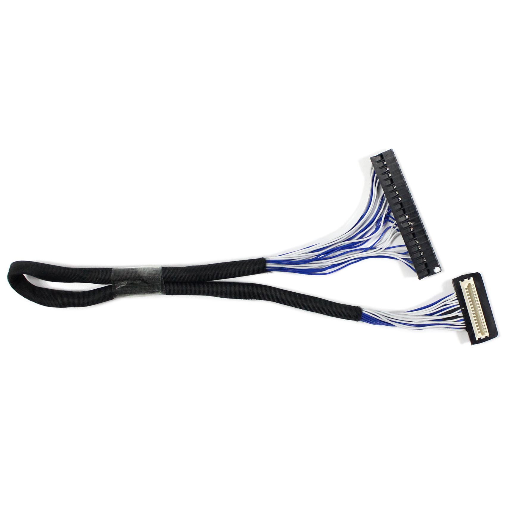
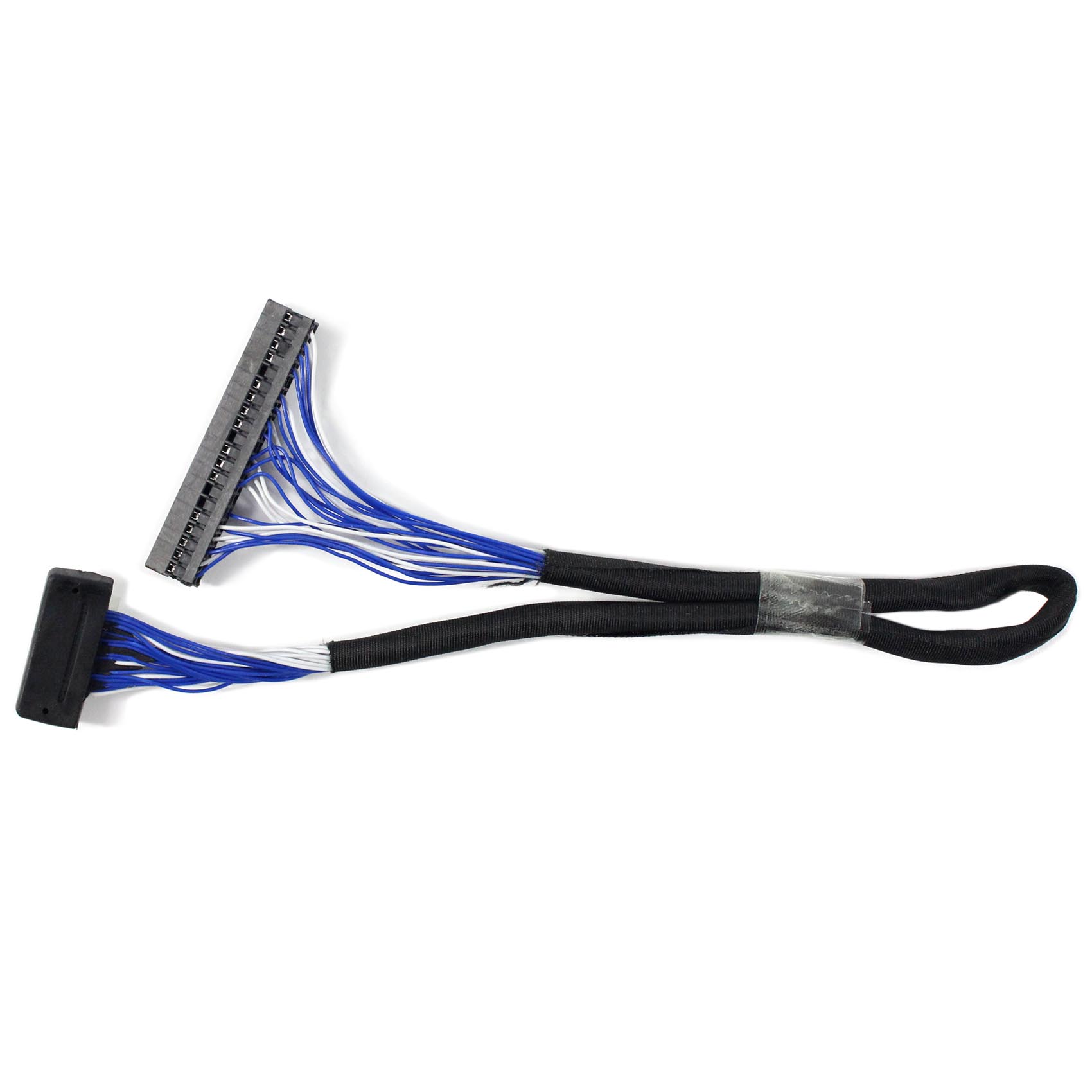
Connection the LCD Controller Board:
PIN # | SIGNAL NAME | DESCRIPTION |
1 | VSEL | Power for panel |
2 | VSEL | Power for panel |
3 | VSEL | Power for panel |
4 | VSEL | Power for panel |
5 | GND | Ground |
6 | GND | Ground |
7 | VS | Vertical Synchronous Signal |
8 | GND | Ground |
9 | HS | Horizontal Synchronous Signal |
10 | GND | Ground |
11 | DE | Date Time Control |
12 | GND | Ground |
13 | OR0 | Red Data |
14 | OR1 | Red Date |
15 | OR2 | Red Date |
16 | OR3 | Red Date |
17 | OR4 | Red Date |
18 | OR5 | Red Date |
19 | OR6 | Red Date |
20 | OR7 | Red Date |
21 | GND | Ground |
22 | OG0 | Green Data |
23 | OG1 | Green Data |
24 | OG2 | Green Data |
25 | OG3 | Green Data |
26 | OG4 | Green Data |
27 | OG5 | Green Data |
28 | OG6 | Green Data |
29 | OG7 | Green Data |
30 | GND | Ground |
31 | OB0 | Blue Data |
32 | OB1 | Blue Data |
33 | OB2 | Blue Data |
34 | OB3 | Blue Data |
35 | OB4 | Blue Data |
36 | OB5 | Blue Data |
37 | OB6 | Blue Data |
38 | OB7 | Blue Data |
39 | GND | Ground |
40 | CLK | Clock Signal for sample each data signal |
Connection the LCD Screen
PIN # | SIGNAL NAME | DESCRIPTION |
1 | GND | Ground |
2 | CLK | Dot clock |
3 | Hsync | Horizontal sync |
4 | Vsync | Vertical sync |
5 | GND | Ground |
6 | R0 | Red Data |
7 | R1 | Red Date |
8 | R2 | Red Date |
9 | R3 | Red Date |
10 | R4 | Red Data |
11 | R5 | Red Date |
12 | GND | Ground |
13 | G0 | Green Data |
14 | G1 | Green Data |
15 | G2 | Green Data |
16 | G3 | Green Data |
17 | G4 | Green Data |
18 | G5 | Green Data |
19 | GND | Ground |
20 | B0 | Red Date |
21 | B1 | Blue Date |
22 | B2 | Blue Date |
23 | B3 | Blue Date |
24 | B4 | Blue Date |
25 | B5 | Blue Date |
26 | GND | Ground |
27 | DE | Date enable |
28 | VCC | Power Supply |
29 | VCC | Power Supply |
30 | HREV | Horizontal Image Shift-direction select Signal |
31 | HREV | Vertical Image Shift-direction select Signal |
Packing list :
1× 31P COMS TTL Signal Cable For D9B-31P-1V