1PCS Kelly controller KEB72301X 3KW 72V for electric motorcycles and electric scooters
Shipping list:
Kelly controller*1
J2 line*1
Computer debugging line*1
Shipping list:
Kelly controller*1
J2 line*1
Computer debugging line*1
Peak current: 150A Continuous current: 60A Power: 3KW
Adapter motor power: 800W-1500W Voltage: 72V
Adapter motor power: 800W-1500W Voltage: 72V
Remarks:Remarks:
1. The difference between power generation and no power generation: the power generation function is that the controller recharges a certain amount of power to the battery to increase the cruising range.
The Kelly controller has three power generation modes: brake switch power generation, power generation when the pedal is released, and 0-5V analog signal power generation.
Generally, the car is a friend of lithium batteries. We recommend using a controller without power generation function to avoid over-current protection when the controller generates power.
2. Peak current and continuous current: The peak current is the so-called phase current, and the continuous current is the bus current. The current can be adjusted.
characteristic
• Designed for electric motorcycles and electric scooters• Powerful and intelligent microprocessor• High-speed low-loss synchronous rectification PWM modulation• Strict current limit and torque control• Limit battery current to only half of the maximum phase current of the controller• Larger starting current, faster starting speed can be obtained•Anti-electromagnetic interference, strong anti-vibration performance•Fault indicator lights indicate various faults, which is convenient for users to detect and maintain• Equipped with battery protection function: when the battery voltage is low, it will give an alarm and current attenuation in time, and stop the output when it is too low to protect the battery•Beautiful and fast heat dissipation aluminum shell with spurs•With over-temperature protection function: when the temperature is too high or too low, the current will be attenuated automatically to protect the controller and battery• Compatible with 60 degree or 120 degree Hall position sensor• Support any number of poles brushless motor• Up to 60,000 electrical speeds. (Electrical speed = actual speed * motor pole number)• The brake switch is used to control the entry into regenerative braking.• 0-5V brake signal is used to control the intensity of regenerative braking• High pedal protection: when the key is turned on, the pedal signal will be detected, and if there is a valid signal, it will not be output• Three power generation modes: power generation by brake switch, power generation when the pedal is released, power generation by 0-5V analog signal• Current multiplication: a small battery current can obtain a larger motor output current• Easy to install: use a 3-wire pedal potentiometer to work
basic skills
• Fault detection and protection. The fault can be identified by the LED flashing code.•Real-time monitoring of battery voltage. Too high or too low battery voltage will weaken the output and stop working.• Built-in current loop and overcurrent protection.• The controller has temperature measurement and protection functions.• The controller has temperature measurement and protection functions. In low and high temperature conditions, current reduction will be performed to protect the controller and battery. If the temperature of the controller is higher than 90°C, the current will drop sharply, and the output will be cut off automatically when it reaches 100°C. At low temperatures, the current usually starts to drop at 0°C.• During power generation, the voltage will always be in the state of being monitored by the controller. If the voltage is found to be too high, the controller will immediately cut the current until it stops generating power.• The maximum speed during commutation can be configured to be half of the maximum forward speed.• The controller can be configured by connecting the computer serial port, and the software can be updated. The controller configuration program can run on all Windows versions.• Provide 5V sensor power supply.• 3 switch inputs. It is a valid signal when connected to GND. The default is pedal safety switch input (need to be configured through customer software), brake switch input and reversing switch input.• 3 0-5V analog inputs. The default is pedal analog signal input, brake analog signal input and motor temperature sensor analog signal input.• Configurable Boost switch. After the switch is turned on, the controller will output the maximum current it can reach.• Configurable Turbo switch. After the switch is turned on, the maximum drive current of the controller is limited to half of the normal situation.• The maximum current in configurable commutation is half of the maximum forward current.• Enhanced power brake function. The original ABS brake technology makes your brakes more powerful and stable.• 12V brake signal input can be configured.• Motor over-temperature detection and protection (need to use our designated semiconductor temperature sensor KTY83-122).• 3-phase Hall position sensor input, open collector output, and the controller provides pull-up resistors.• Optional controller control power range 8--30V.
Controller port definition
1. Schematic diagram of the controller panel wiring terminal:
1. Schematic diagram of the controller panel wiring terminal:
Controller port definitionController port definition
1. Schematic diagram of the controller panel wiring terminal:
1. Schematic diagram of the controller panel wiring terminal:
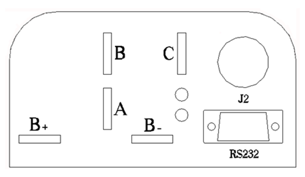
Figure 1: KEB brushless motor controller panel
B+: battery positive
B-: battery negative
A: Output U/1/A phase, even the thick yellow wire of the motor
B: Output V/2/B phase, even the thick green wire of the motor
C: Output W/3/C phase, even the thick blue wire of the motor
RS232: connect to the computer to debug the controller parameter interface
2. The pin definition of the J2 aviation plug of the controller:
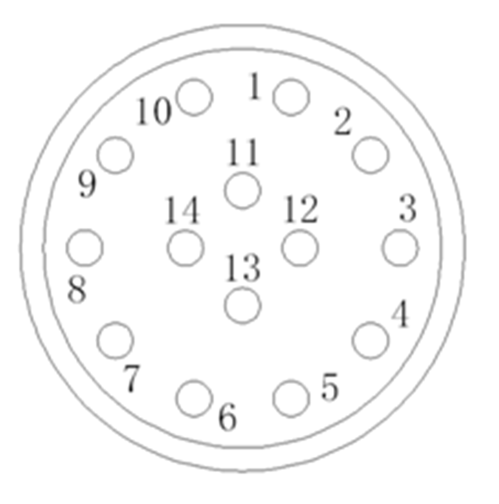
Figure 2: Schematic diagram of the pin location of J2Figure 2: Schematic diagram of the pin location of J2
To
Pin 1: PWR: Control power input.
Pin 2: GND: signal ground, or power ground.
Pin 3: GND: signal ground.
Pin 4: Motor temperature sensor or high-level brake input.
5th foot: pedal analog input, 0-5V.
Foot 6: Brake analog input, 0-5V.
Pin 7: 5V, 5V power output, <40mA.
Foot 8: Pedal safety switch input.
Pin 9: Reversing switch input.
Foot 10: Brake switch input.
Pin 11: Hall C phase, connected to the thin blue Hall signal wire of the motor.
Pin 12: Hall B phase, connected to the thin green Hall signal wire of the motor.
Pin 13: Hall A phase, connected to the thin yellow Hall signal wire of the motor.
The 14th foot: GND, signal ground.
Wiring instructions
1. High voltage wire connection:
(1) B+ is connected to the positive electrode of the battery, preferably through an air switch, so as to increase the safety of the vehicle
(2) B-Connect the negative pole of the battery
(3) Phase wires of A, B, and C connected to the motors (Transit motor, other motors need to be tested to know the wiring) yellow, green, and blue
2. Low-voltage signal line wiring:
(1) Electric door lock: Line 1 is connected to B+ or no less than 12V through the electric door lock
(2) Handlebar: Line 2 or 3, 5, 7 is connected to the handlebar, wire 2 or 3 is the ground wire, connected to the negative of the handlebar, line 7 is a 5V power supply, connected to the positive of the handlebar, No. 5 It is the signal line for connecting and turning the handle.
(3) High-level brake: Line 4 is connected to 12V for high-level brake (most of the brakes are connected to Line 4)
(4) Low-level brake: Connecting line 10 to line 2 or 3 is a low-level brake.
(5) Reversing gear: 9 is connected to line 2 is the reverse line (electric motorcycle users can choose not to connect).
(6) Boost or Economy function: Connecting line 6 to line 7 is an instantaneous acceleration switch or an economy mode switch (you need to enable the function on the software to work, and the two cannot be used at the same time. Turn on the instantaneous acceleration (boost), this When the switch is closed, it will accelerate instantly, and when the economy mode function is turned on, the speed and current will decrease when the switch is opened.)
(7) Motor Hall wire: Line 2 or 3, 7, 11, 12, 13, of which line 2 or 3 is grounded, line 7 is connected to 5V or 12V power supply, line 11, 12, and 13 are connected to motor ( Transit Motor) Three Hall wires in yellow, green and blue
(8) Pedal safety switch input:
① It can be used as a safety switch. If it is connected to the bracket, there is no output when the bracket is not stowed and the throttle is turned on, which can increase safety.
②It can be used as a three-speed controller (electric motorcycle users can choose not to use)
(9) Brake analog input: (electric motorcycle users can choose not to connect)
(10) Wiring of the controller with alarm function: only 4 wires for the alarm (generally 5 wires for the alarm, 4 wires for the Kelly controller), one power input, one power output, and one ground wire , A lock motor line. (Because there are various alarms on the market, it takes time to study)
①B+ (with ring) from the aviation plug of Kelly's special J2 harness is connected to B+ of the controller (to ensure that the main electrical circuit cannot be disconnected). ②Connect the B+ wire out of the wire harness to the power wire (yellow wire PWR) of the alarm. ③ Line 2 is connected to the ground wire of the alarm. ④ Line 1 in the alarm plug-in is connected to the power output line of the alarm. ⑤ No. 8 is the motor lock function, connected to the signal output line of the alarm (low level alarm).
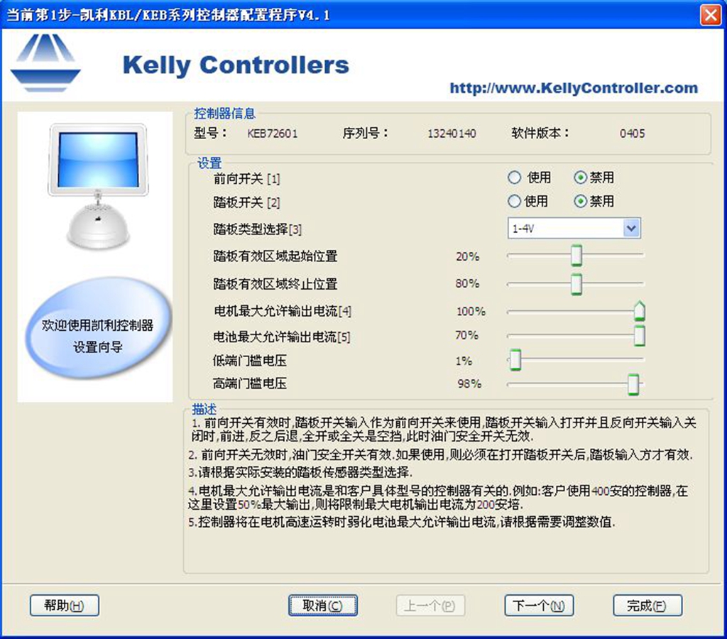
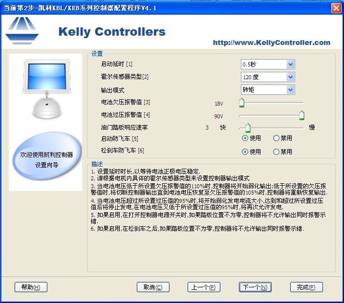
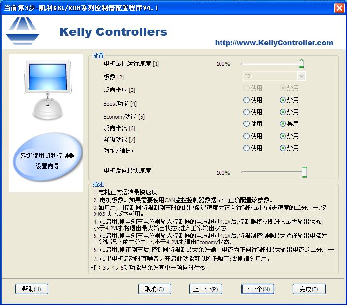
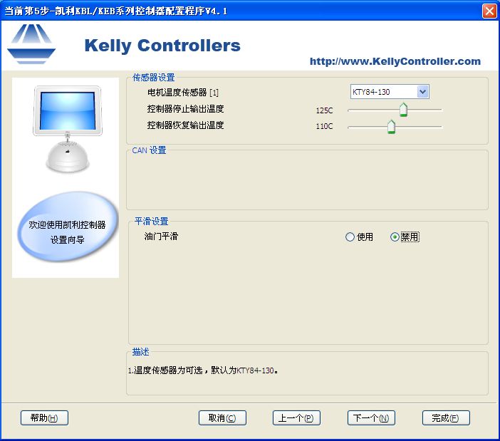
Kelly KEB controller debugging demonstration
To
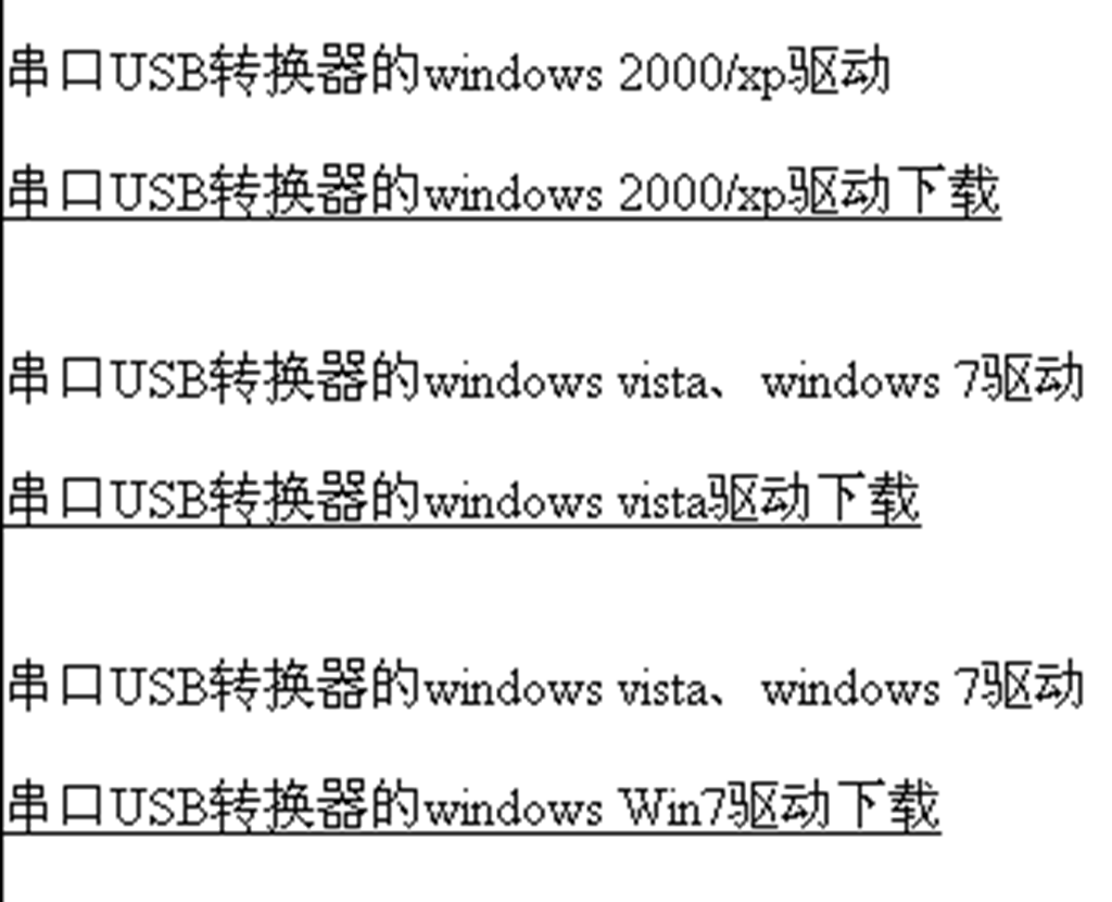
1. First, you need to download the debugging software and drivers on the Kelly official website. Download URL: http://www.kellycontroller.com/china/Support.html 与此原文有关的更多信息要查看其他翻译信息,您必须输入相应原文
1. High voltage wire connection:
(1) B+ is connected to the positive electrode of the battery, preferably through an air switch, so as to increase the safety of the vehicle
(2) B-Connect the negative pole of the battery
(3) Phase wires of A, B, and C connected to the motors (Transit motor, other motors need to be tested to know the wiring) yellow, green, and blue
2. Low-voltage signal line wiring:
(1) Electric door lock: Line 1 is connected to B+ or no less than 12V through the electric door lock
(2) Handlebar: Line 2 or 3, 5, 7 is connected to the handlebar, wire 2 or 3 is the ground wire, connected to the negative of the handlebar, line 7 is a 5V power supply, connected to the positive of the handlebar, No. 5 It is the signal line for connecting and turning the handle.
(3) High-level brake: Line 4 is connected to 12V for high-level brake (most of the brakes are connected to Line 4)
(4) Low-level brake: Connecting line 10 to line 2 or 3 is a low-level brake.
(5) Reversing gear: 9 is connected to line 2 is the reverse line (electric motorcycle users can choose not to connect).
(6) Boost or Economy function: Connecting line 6 to line 7 is an instantaneous acceleration switch or an economy mode switch (you need to enable the function on the software to work, and the two cannot be used at the same time. Turn on the instantaneous acceleration (boost), this When the switch is closed, it will accelerate instantly, and when the economy mode function is turned on, the speed and current will decrease when the switch is opened.)
(7) Motor Hall wire: Line 2 or 3, 7, 11, 12, 13, of which line 2 or 3 is grounded, line 7 is connected to 5V or 12V power supply, line 11, 12, and 13 are connected to motor ( Transit Motor) Three Hall wires in yellow, green and blue
(8) Pedal safety switch input:
① It can be used as a safety switch. If it is connected to the bracket, there is no output when the bracket is not stowed and the throttle is turned on, which can increase safety.
②It can be used as a three-speed controller (electric motorcycle users can choose not to use)
(9) Brake analog input: (electric motorcycle users can choose not to connect)
(10) Wiring of the controller with alarm function: only 4 wires for the alarm (generally 5 wires for the alarm, 4 wires for the Kelly controller), one power input, one power output, and one ground wire , A lock motor line. (Because there are various alarms on the market, it takes time to study)
①B+ (with ring) from the aviation plug of Kelly's special J2 harness is connected to B+ of the controller (to ensure that the main electrical circuit cannot be disconnected). ②Connect the B+ wire out of the wire harness to the power wire (yellow wire PWR) of the alarm. ③ Line 2 is connected to the ground wire of the alarm. ④ Line 1 in the alarm plug-in is connected to the power output line of the alarm. ⑤ No. 8 is the motor lock function, connected to the signal output line of the alarm (low level alarm).
Kelly KEB controller debugging demonstration
To
1. First, you need to download the debugging software and drivers on the Kelly official website. Download URL: http://www.kellycontroller.com/china/Support.html 与此原文有关的更多信息要查看其他翻译信息,您必须输入相应原文
2. After downloading and installing, the computer desktop will appear:
Packing:1PC
Warranty period: 120 days
