

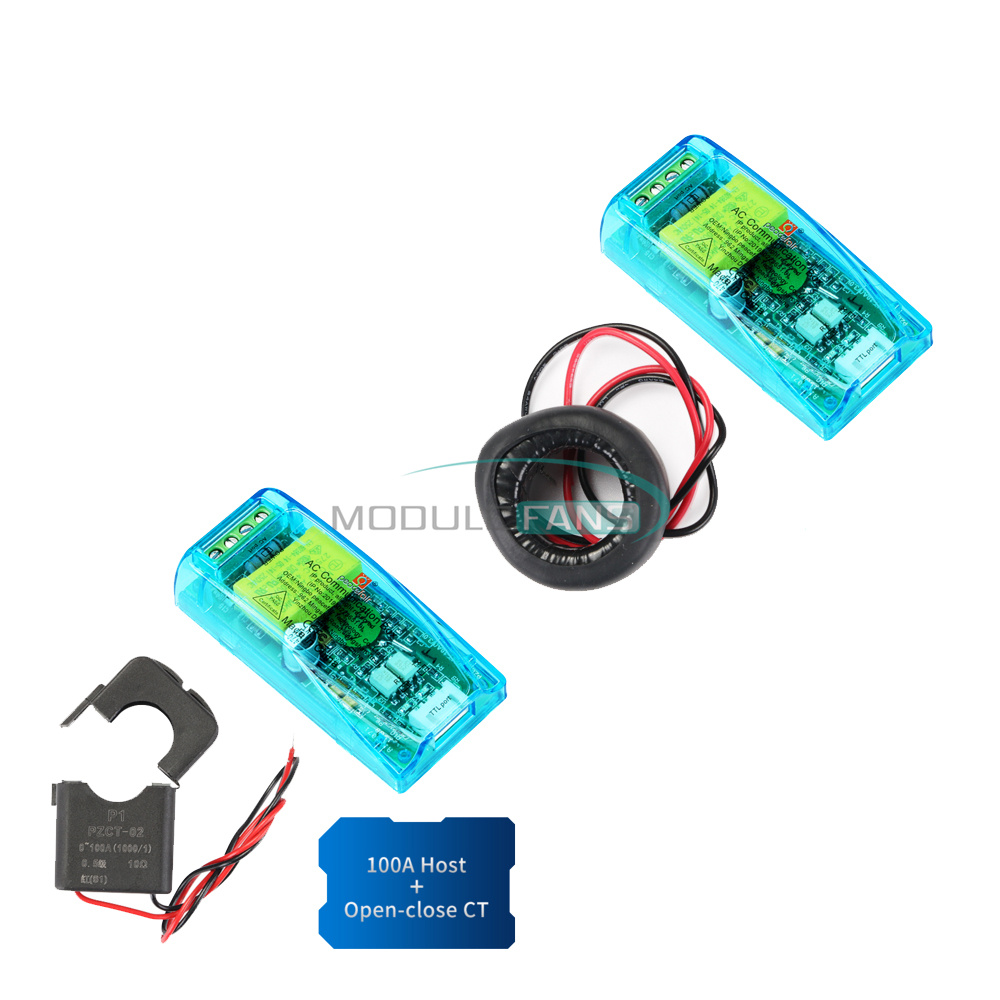
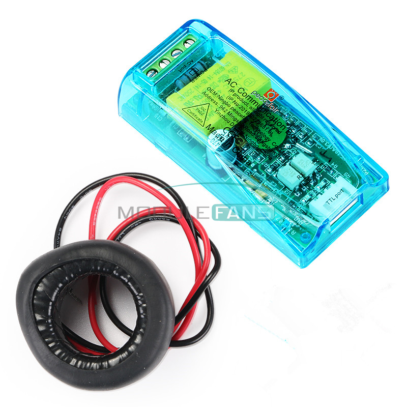
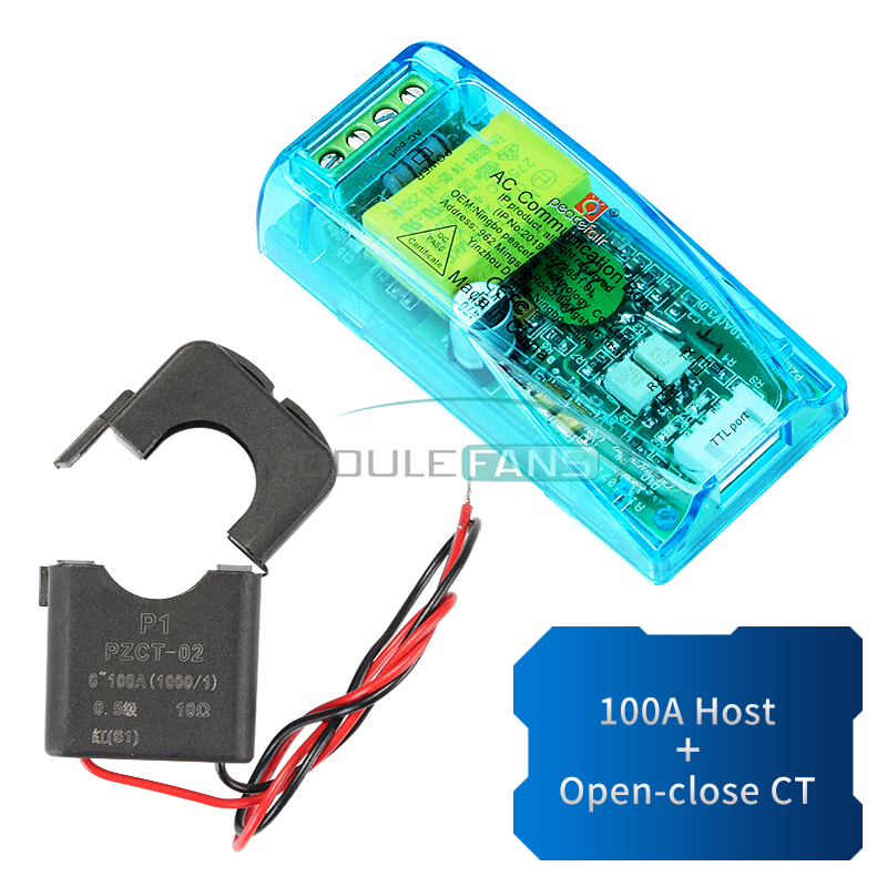


AC communication module
Overview
This document describes the specification of the PZEM-004T AC communication module, the module is mainly used for measuring AC voltage, current, active power, frequency, power factor and active energy, the module is without display function, the data is read through the TTL interface.
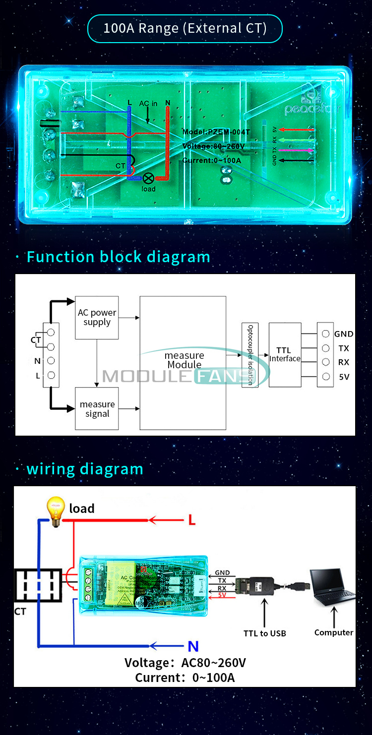
PZEM-004T-100A: Measuring Range 100A (external transformer)
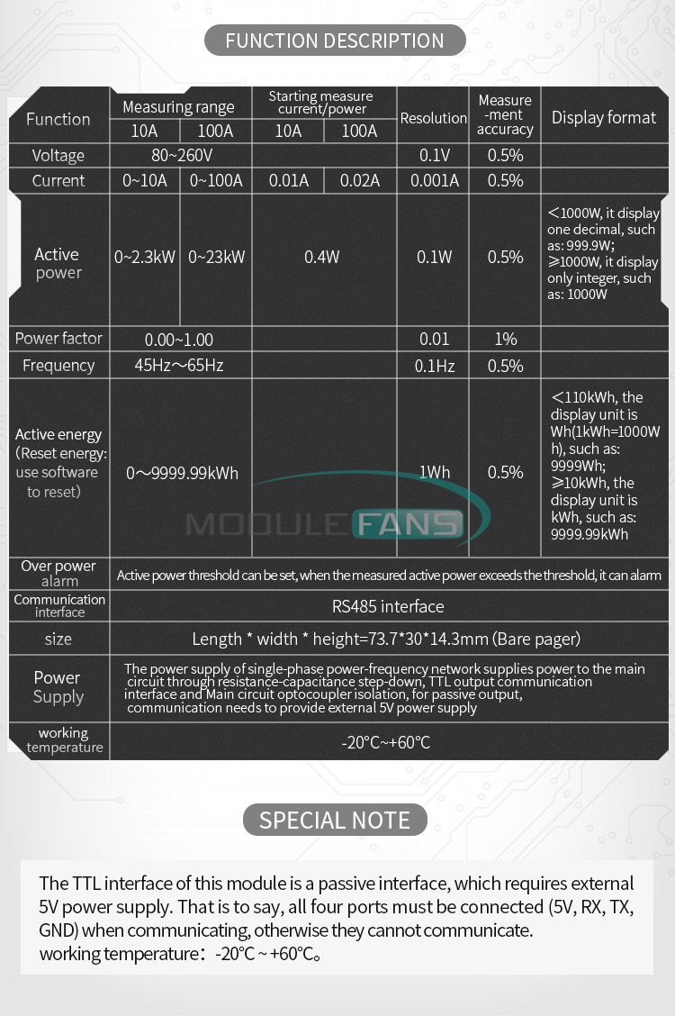
1.Function description
<1000W, it display one decimal, such as: 999.9W
≥1000W, it display only integer, such as: 1000W
<10kWh, the display unit is Wh(1kWh=1000Wh), such as: 9999Wh
≥10kWh, the display unit is kWh, such as: 9999.99kWh
Active power threshold can be set, when the measured active power exceeds the threshold, it can alarm
RS485 interface。
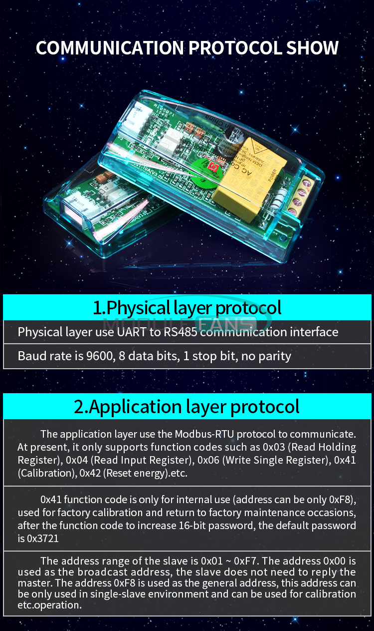
2 Communication protocol
Physical layer use UART to RS485 communication interface
Baud rate is 9600, 8 data bits, 1 stop bit, no parity
The application layer use the Modbus-RTU protocol to communicate. At present, it only supports function codes such as 0x03 (Read Holding Register), 0x04 (Read Input Register), 0x06 (Write Single Register), 0x41 (Calibration), 0x42 (Reset energy).etc.
0x41 function code is only for internal use (address can be only 0xF8), used for factory calibration and return to factory maintenance occasions, after the function code to increase 16-bit password, the default password is 0x3721
The address range of the slave is 0x01 ~ 0xF7. The address 0x00 is used as the broadcast address, the slave does not need to reply the master. The address 0xF8 is used as the general address, this address can be only used in single-slave environment and can be used for calibration etc.operation.
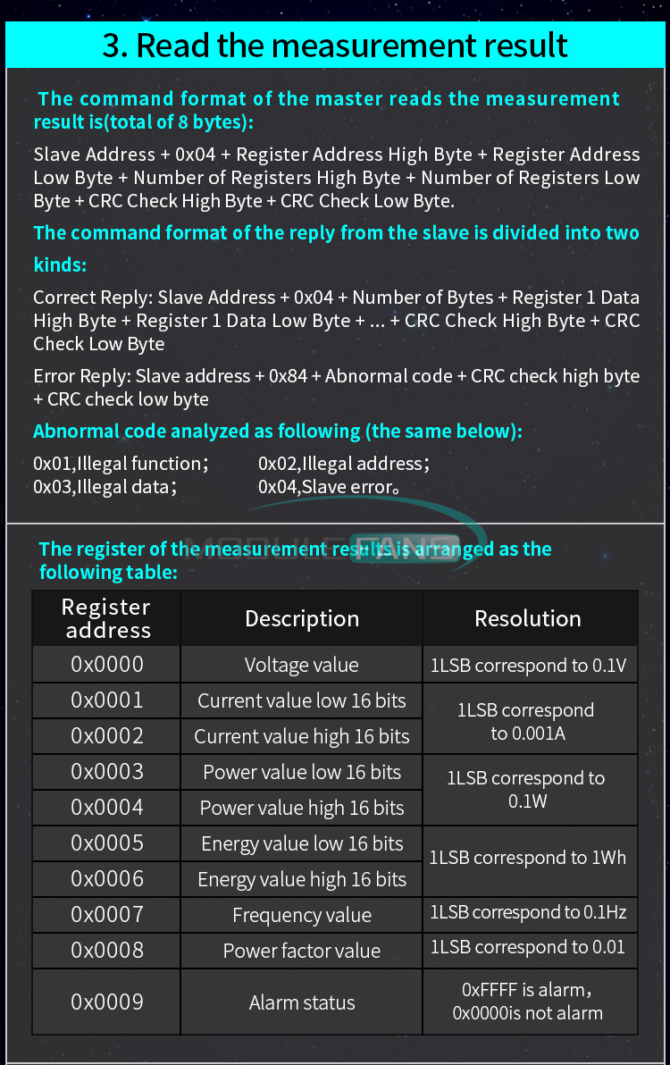
The command format of the master reads the measurement result is(total of 8 bytes):
Slave Address + 0x04 + Register Address High Byte + Register Address Low Byte + Number of Registers High Byte + Number of Registers Low Byte + CRC Check High Byte + CRC Check Low Byte.
The command format of the reply from the slave is divided into two kinds:
Correct Reply: Slave Address + 0x04 + Number of Bytes + Register 1 Data High Byte + Register 1 Data Low Byte + ... + CRC Check High Byte + CRC Check Low Byte
Error Reply: Slave address + 0x84 + Abnormal code + CRC check high byte + CRC check low byte
Abnormal code analyzed as following (the same below)
|
Register address |
Description |
Resolution |
|
0x0000 |
Voltage value |
1LSB correspond to 0.1V |
|
0x0001 |
Current value low 16 bits |
1LSB correspond to 0.001A |
|
0x0002 |
Current value high 16 bits |
|
|
0x0003 |
Power value low 16 bits |
1LSB correspond to 0.1W |
|
0x0004 |
Power value high 16 bits |
|
|
0x0005 |
Energy value low 16 bits |
1LSB correspond to 1Wh |
|
0x0006 |
Energy value high 16 bits |
|
|
0x0007 |
Frequency value |
1LSB correspond to 0.1Hz |
|
0x0008 |
Power factor value |
1LSB correspond to 0.01 |
|
0x0009 |
Alarm status |
0xFFFF is alarm,0x0000is not alarm |
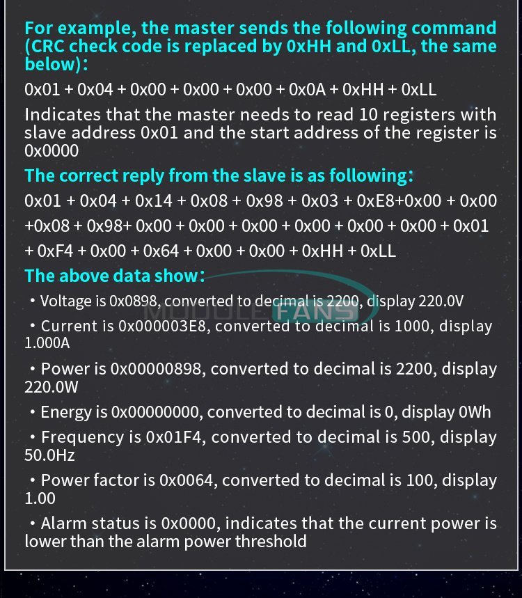
For example, the master sends the following command (CRC check code is replaced by 0xHH and 0xLL, the same below)
0x01 + 0x04 + 0x00 + 0x00 + 0x00 + 0x0A + 0xHH + 0xLL
Indicates that the master needs to read 10 registers with slave address 0x01 and the start address of the register is 0x0000
The correct reply from the slave is as following:
0x01 + 0x04 + 0x14 + 0x08 + 0x98 + 0x03 + 0xE8+0x00 + 0x00 +0x08 + 0x98+ 0x00 + 0x00 + 0x00 + 0x00 + 0x00 + 0x00 + 0x01 + 0xF4 + 0x00 + 0x64 + 0x00 + 0x00 + 0xHH + 0xLL
The above data shows
At present,it only supports reading and modifying slave address and power alarm threshold
The register is arranged as the following table
|
Register address |
Description |
Resolution |
|
0x0001 |
Power alarm threshold |
1LSB correspond to 1W |
|
0x0002 |
Modbus-RTU address |
The range is 0x0001~0x00F7 |
The command format of the master to read the slave parameters and read the measurement results are same(descrybed in details in Section 2.3), only need to change the function code from 0x04 to 0x03.
The command format of the master to modify the slave parameters is (total of 8 bytes):
Slave Address + 0x06 + Register Address High Byte + Register Address Low Byte + Register Value High Byte + Register Value Low Byte + CRC Check High Byte + CRC Check Low Byte.
The command format of the reply from the slave is divided into two kinds:
Correct Response: Slave Address + 0x06 + Number of Bytes + Register Address Low Byte + Register Value High Byte + Register Value Low Byte + CRC Check High Byte + CRC Check Low Byte.
Error Reply: Slave address + 0x86 + Abnormal code + CRC check high byte + CRC check low byte.
For example, the master sets the slave's power alarm threshold:
0x01 + 0x06 + 0x00 + 0x01 + 0x08 + 0xFC + 0xHH + 0xLL
Indicates that the master needs to set the 0x0001 register (power alarm threshold) to 0x08FC (2300W).
Set up correctly, the slave return to the data which is sent from the master.
For example, the master sets the address of the slave
0x01 + 0x06 + 0x00 + 0x02 + 0x00 + 0x05 + 0xHH + 0xLL
Indicates that the master needs to set the 0x0002 register (Modbus-RTU address) to 0x0005
Set up correctly, the slave return to the data which is sent from the master.
The command format of the master to reset the slave's energy is (total 4 bytes):
Slave address + 0x42 + CRC check high byte + CRC check low byte.
Correct reply: slave address + 0x42 + CRC check high byte + CRC check low byte.
Error Reply: Slave address + 0xC2 + Abnormal code + CRC check high byte + CRC check low byte
The command format of the master to calibrate the slave is (total 6 bytes):
0xF8 + 0x41 + 0x37 + 0x21 + CRC check high byte + CRC check low byte.
Correct reply: 0xF8 + 0x41 + 0x37 + 0x21 + CRC check high byte + CRC check low byte.
Error Reply: 0xF8 + 0xC1 + Abnormal code + CRC check high byte + CRC check low byte.
It should be noted that the calibration takes 3 to 4 seconds, after the master sends the command, if the calibration is successful, it will take 3 ~ 4 seconds to receive the response from the slave.
CRC check use 16bits format, occupy two bytes, the generator polynomial is X16 + X15 + X2 +1, the polynomial value used for calculation is 0xA001.
The value of the CRC check is a frame data divide all results of checking all the bytes except the CRC check value.
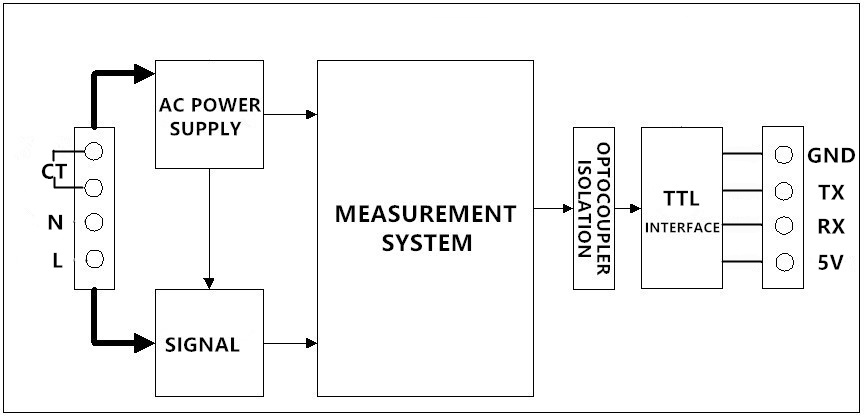
3 Functional block diagram
Picture 3.1 PZEM-004T-10A Functional block diagram
2. We ship your orders within 1-2 business days after the payment cleared.
3. Item shipped from China via china Post Airmail, reach most of the countries within 2 to 4 weeks.
4. Delivery time depends on destination and other factors, it may takes up to 20 days. If you don't receive
the item after 30 days,please keep in touch with us, we'll investigate and solve the delivery problem.
5. Import duties, taxes, and charges are not included in the item price or shipping cost. These charges
are the buyer's responsibility. Please check with your country's customs office to determine what these
additional costs will be prior to bidding or buying.
1. We accept PAYPAL only.
2. Payment must be made within 7 days of auction closing (Unpaid dispute will automatically open when item
is not paid in 7 days).
3. PLEASE NOTE: SHIPPING&HANDING DOES NOT INCLUDE DUTIES, LOCATL TAXES OR ANY OTHER IMPORTATION FEES.
4. Please list your special requests (color, packages, value of declaration, etc.) in the EBAY NOTES SECTION
when you make payment
condition when shipped to our customers. If product is defective or damage upon arrival, or wrong
product shipped, please keep in touch with us immediately. Returns accepted within 14 days of delivery date
and item must be in original new condition, not worn or altered in any way with attached tags & wrap.
Otherwise deal is final. Return shipping must be paid by buyer.
2. Please keep in touch with us first if you have anyproblems/questions/concerns. We will be happy to resolve
any issues you may have in a cordial and friendly manner.
3. We appreciate your Positive Feedback, and will do the same in return. PLEASE DO NOT leave
negative feedback without first communication with us. Please allow max 24 HOURS for us to respond
We maintain high standards of excellence and strive for 100% customer satisfaction! Feedback is
very important to us. We request that you keep in touch with us immediately BEFORE you give us neutral or
negative feedback, so that we can satisfactorily address your concerns.It is impossible to address
issues if we do not know about them!
