 |  |  |  |
| Description |
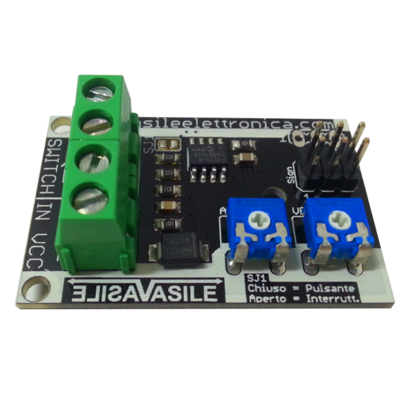
The control for servo (cod. VE015-008), allows to manage, through the use of a button or switch (selectable with a solder pad on the board) two servos with parallel displacement and, if necessary, manage a third actuator with push-pull displacement.
The circuit simplicity combined with the reduced dimensions allows the use of this module in the most varied applications where a mechanical control is required.
|
| Technical data |
- Power supply voltage: 4 - 7Vdc;
- Absorption: 100mA (Max) at 7Vcc;
- Speed adjustment: single-turn linear trimmer;
- Opening angle adjustment: single-turn linear trimmer;
- Supported servos: Analog and digital;
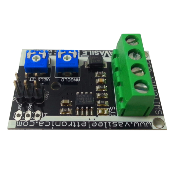
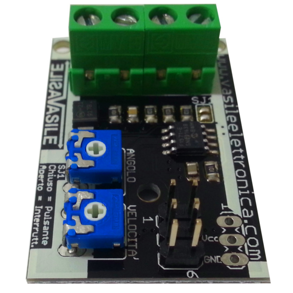
- Six-pin connector for parallel connection of two servos;
- Three-pin connector for the connection of the servo with rotation in push-pull;
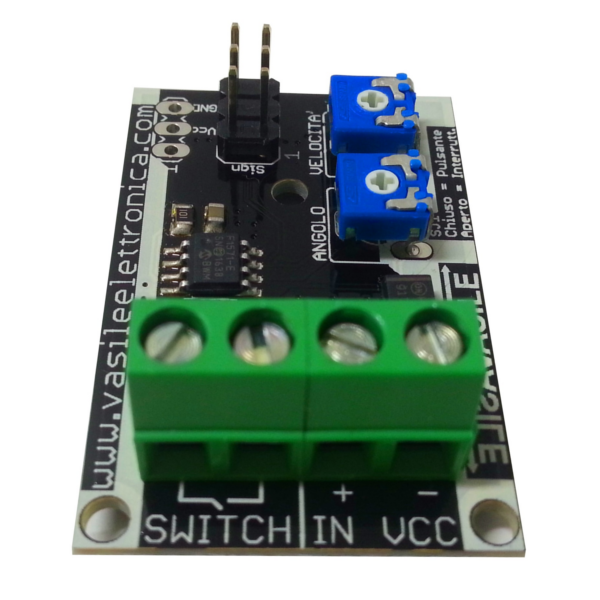
- 2-pin terminal block for the connection of the button or switch;
- Operation with button or switch selectable directly from the board.
|
| Using the circuit |
The servo control allows you to manage analogue and digital servos in a simple and economical way.
The control is entrusted to the 8-bit microprocessor "12F1571" Microchip, it:
- monitors the status of the input for the button;
- it takes the angular position and the speed of movement from the two trimmers;
- generates a PWM signal for motor controls.
The opening angle is adjustable by acting on the trimmer "ANGLE", turning to the left, the opening angle of the servo increases, turning to the right, the opening angle decreases.
The movement speed is adjustable by acting on the trimmer "SPEED', turning to the right, the speed decreases, turning to the left, the speed of the servo increases.
The jumper "SJ1" allows you to select the operating mode:
 | - SJ1 closed: push button operation;
- SJ1 open: switch operation;
The closure of the jumper must be done with a welding. |
|
| Operation of the "Push-pull" system |
We attribute the name SERVO2 to the servo wired to the single connector, e SERVANT 1 to the one wired on the double connector; as soon as power is supplied to the circuit, the SERVANT 1 moves to the rest position at an angle of 0 °, while the SERVO2 moves to the resting position at an angle of 180 °.
By pressing the key that activates the movement, the two servos begin to move with the speed set by the trimmer "SPEED'" and continue running until they reach the angle set with the trimmer "ANGLE".
Ex:
- displacement angle set a 40 °, the SERVANT 1 assumes an angle of 40 ° while the SERVO2 from 140 °;
- displacement angle set a 170 °, the SERVANT 1 assumes an angle of 170 ° while the SERVO2 from 10 °;
|
| Adjustment |
After making all the connections listed above, proceed as follows for the adjustment:
- Rotate the trimmers (ANGLE And SPEED') in the central position;
- Supply power to the circuit (the servos moves to the initial position, ie the rest position);
- Press the wired button or switch on the input SWITCH (the servos rotate up to the opening position adjusted by the trimmer);
- Act on the trimmer ANGLE to adjust the desired opening angle and act on the trimmer SPEED' to adjust the running speed.
|
|
| Video |
 Control for servo - YouTube |