High precision screen printing table manual plane screen printing table hand printing table small Solder Paste Printer
Model: ZB3040H
Table size: 300*400 mm
Maximum printing size: 250*400 mm
Maximum frame size: 370*470 mm
Printing speed: manual control
Printing thickness: 0~80 mm
Worktable vertical and horizontal adjustment: 10 mm
Printing platform height: 220 mm
Repeat printing accuracy: ±0.01 mm
Positioning method: shape or reference hole
Dimensions: 540*370*380 mm
Net weight: 23 kg
Precision screen printing is mainly designed for single and double-sided circuit board pasting or red glue printing. The working platform is made of high-quality aluminum plate with honeycomb positioning holes, and the bottom plate is welded with thickened steel plate, which is firm and durable.
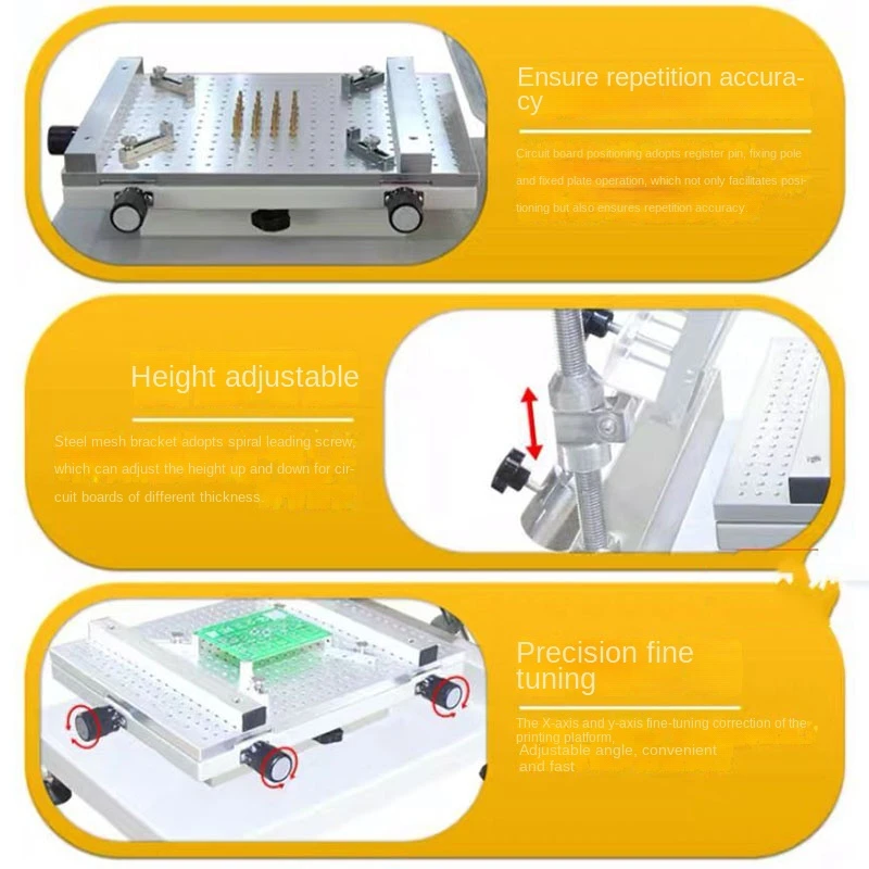
The circuit board adopts positioning pins, and the fixed rods are positioned with the fixed plate, which is convenient for positioning and ensures the accuracy of repeated operations.
The correction method is moved by the steel mesh and adjusted by fine-tuning the X and Y axes of the printing platform
The wire frame adopts a screw screw, which can adjust the height up and down to control the thickness of the PCB and the amount of printing paste
The printing screen is fixed with 4 pressure plate knobs, fast and firm
Install:
Unpack it, read the instructions carefully, and hold the main frame with both hands. Lift the console and place the console in the correct orientation. The ground needs to be firm and smooth
Adjust the four adjustment feet of the base to keep the whole machine horizontal and stable
Install the printing plate, adjust the position and angle of the counterweight and the fixed handle, so that the printing plate is always in the proper angular position
Operation:
Step 1: Take off the printed circuit board, put it on the four positioning pins, rotate the height adjustment knob to make the printed module contact the circuit board, and then adjust the position of the positioning pins to make the printing holes of the printing template consistent with the printing surface of the circuit board, and fix it. Four positioning pins
Step 2: According to the size of the circuit board and the position of the board, place the corresponding thimble between the four positioning pin positions, and adjust the X and Y axis adjustment knobs to accurately locate the printing surface and hole positions of the printed circuit board printing template. Secured by locking knob.
Step 3: Remove the corresponding solder paste according to the printed circuit board or take a small amount of solder paste and place it in the template (Note: The solder paste must be fully mixed after use, it is recommended to use ZB500S constant temperature automatic solder paste mixer), use a scraper to put the solder paste in the template. The appropriate position is evenly drawn across the printing position as a template. Complete the operation once, do not repeat the operation
Step 4: After printing, if the amount of solder paste on the circuit board is less or more, the gap between the printing template and the circuit board can be adjusted through the template height adjustment knob to control the amount of solder paste printed on the circuit board.
Step 5: After the printed circuit board is made, the excess solder paste should be placed in another container, and the original unused solder paste cannot be returned to avoid damage to the unused solder paste and printing stencils and scraper cleaning, generally used Medical alcohol cleaning
matter:
1: After each work is completed, clean and maintain the machine in time to avoid affecting the service life of the machine
2: The printing template moves up and down, do not use too much force, so as not to damage the machine and affect the positioning accuracy
3: When picking and placing the circuit board, pay attention to protect the positioning pins to avoid damage. For positioning holes of different sizes, you can also match the corresponding positioning pins


Model: ZB3040H
Table size: 300*400 mm
Maximum printing size: 250*400 mm
Maximum frame size: 370*470 mm
Printing speed: manual control
Printing thickness: 0~80 mm
Worktable vertical and horizontal adjustment: 10 mm
Printing platform height: 220 mm
Repeat printing accuracy: ±0.01 mm
Positioning method: shape or reference hole
Dimensions: 540*370*380 mm
Net weight: 23 kg
Precision screen printing is mainly designed for single and double-sided circuit board pasting or red glue printing. The working platform is made of high-quality aluminum plate with honeycomb positioning holes, and the bottom plate is welded with thickened steel plate, which is firm and durable.
The circuit board adopts positioning pins, and the fixed rods are positioned with the fixed plate, which is convenient for positioning and ensures the accuracy of repeated operations.
The correction method is moved by the steel mesh and adjusted by fine-tuning the X and Y axes of the printing platform
The wire frame adopts a screw screw, which can adjust the height up and down to control the thickness of the PCB and the amount of printing paste
The printing screen is fixed with 4 pressure plate knobs, fast and firm
Install:
Unpack it, read the instructions carefully, and hold the main frame with both hands. Lift the console and place the console in the correct orientation. The ground needs to be firm and smooth
Adjust the four adjustment feet of the base to keep the whole machine horizontal and stable
Install the printing plate, adjust the position and angle of the counterweight and the fixed handle, so that the printing plate is always in the proper angular position
Operation:
Step 1: Take off the printed circuit board, put it on the four positioning pins, rotate the height adjustment knob to make the printed module contact the circuit board, and then adjust the position of the positioning pins to make the printing holes of the printing template consistent with the printing surface of the circuit board, and fix it. Four positioning pins
Step 2: According to the size of the circuit board and the position of the board, place the corresponding thimble between the four positioning pin positions, and adjust the X and Y axis adjustment knobs to accurately locate the printing surface and hole positions of the printed circuit board printing template. Secured by locking knob.
Step 3: Remove the corresponding solder paste according to the printed circuit board or take a small amount of solder paste and place it in the template (Note: The solder paste must be fully mixed after use, it is recommended to use ZB500S constant temperature automatic solder paste mixer), use a scraper to put the solder paste in the template. The appropriate position is evenly drawn across the printing position as a template. Complete the operation once, do not repeat the operation
Step 4: After printing, if the amount of solder paste on the circuit board is less or more, the gap between the printing template and the circuit board can be adjusted through the template height adjustment knob to control the amount of solder paste printed on the circuit board.
Step 5: After the printed circuit board is made, the excess solder paste should be placed in another container, and the original unused solder paste cannot be returned to avoid damage to the unused solder paste and printing stencils and scraper cleaning, generally used Medical alcohol cleaning
matter:
1: After each work is completed, clean and maintain the machine in time to avoid affecting the service life of the machine
2: The printing template moves up and down, do not use too much force, so as not to damage the machine and affect the positioning accuracy
3: When picking and placing the circuit board, pay attention to protect the positioning pins to avoid damage. For positioning holes of different sizes, you can also match the corresponding positioning pins