


12v / 24v DC PWM Power Fan Controller 10a
Using the potentiometer the user may use this device to control direct current loads (DC Fans, lamps, heating, LEDs with protective resistors, etc).
An adjustable potentiometer can open up many interesting user interfaces. Turn the pot and the resistance changes. Connect VCC to an outer pin, GND to the other, and the center pin will have a voltage that varies from 0 to VCC depending on the rotation of the pot.
| Specification | |
| Operating Voltage | 9 - 28v DC |
| Max Current Capacity | 5a or 10a if the module is fixed to a cooling plate |
| Control Range | Approx. 5 - 95% |
| Input PWM Signal | 10Hz - 10kHz @ 5v |
| Potentiometer | 4.7 k Ohm linear taper, 1/4" mounting diameter |
| Permissible Loads | Direct current motors, incandescent lamps, LEDs with protective resistors. |
| Connections | 6x 6.3mm Spade Terminal |
| Manufacturer | KEMO Electronics |
| Our Part Number | D84-49E-7D4 |
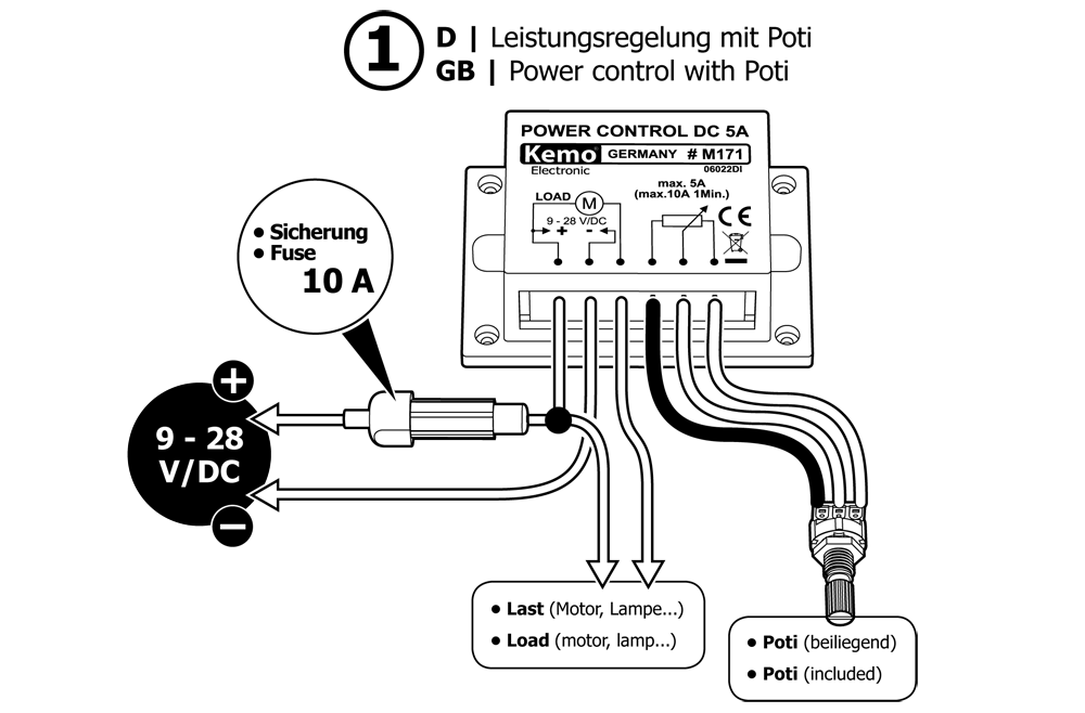

The desired output may be adjusted (controlled) with the potentiometer after switching on the operating voltage.
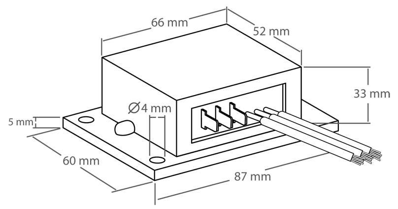
The module may heat depending on the load. Therefore, it has to be mounted in a dry and well ventilated place. In case of loads of more than 5 A (up to max. 10 A) the module with the metallic base area has to be cooled. This is done by attaching it planely on a heat sink or bigger metallic piece (e.g. angle section, metallic plate) in such a manner that the metallic base plate of the module will not heat to more than +70°C under highest load (the connected load runs at max. power).
The operating voltage of the module must be between 9 - 28 V and come up to the operating voltage of the connected load. Example: When operating a 12 V motor the operating voltage must be 12 V.
The operating voltage (e.g. from the battery) and the load (e.g. direct current motor) have to be connected according to the drawing. It is important to keep the cables as short as possible and also to employ cables with a sufficient cross-section (1.5 - 2.5 mm²). If the cable is too thin or too long power losses will occur in the cable and the connected motor runs slower. Furthermore, there is the risk that too thin cables will become hot because very high currents flow.
It is absolutely necessary to connect a fuse 10 A in series according to the connecting diagram!

- This device will still need an ON/OFF switch, simply rotating the Pot to 0% will not turn off the fan.
- For use with our 2 wire single speed fans only.
- The Pot supplied does not currently fit any of our fan knobs, you will need to substitute the Pot for a version that has a 1/4" D shaft. We are currently working on a solution to this problem.