Ship from USA Warehouse fast shipping service to US Customers
Parcel:
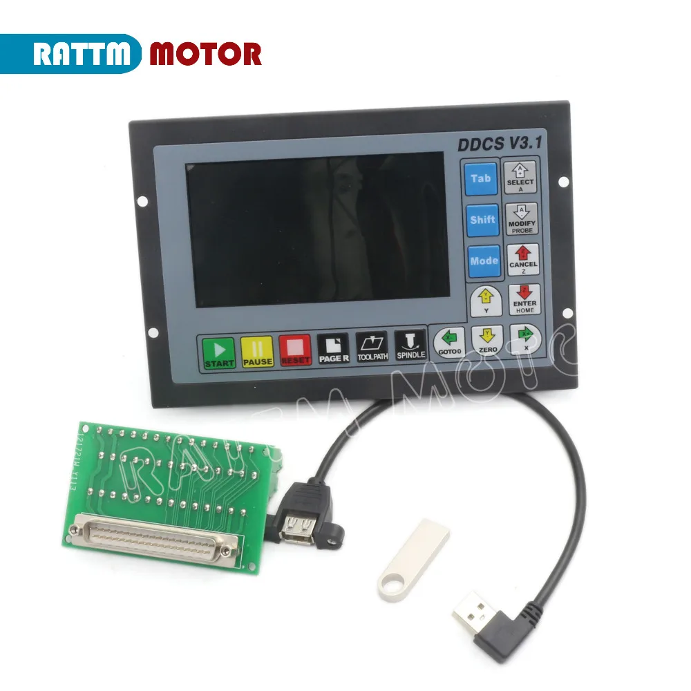
- 1 x 4 Axis CNC offline Stand-alone motion controller (DDCSV3.1)
- 1 x 4GB USB Flash drive
- 1 x USB Extension Cable
- 2 x 75W 24V DC Switching power supply
- English manual
Descriptions:
4 Axis CNC offline Stand-alone motion controller DDCSV3.1

Introduction
- Aims to combine high quality and high reliability with affordability. The DDCS is a 4 axis motion controller for stepper and servo systems. DDCS V3.1 is updated from DDCS V2.1 on software and hardware.We are very proud of this product,it combines great power with a tiny footprint and is easy to use.
- The highest output pulse per axis is 500KHz. This provides high control precision for stepper motors and servo motors.
- The DDCS numerical control system adopts the ARM+FPGA design framework. The ARM can finish the part of human-computer interface and code analysis and the FPGA can finish the part of underlying algorithm and control pulse generate, with the reasonable design, reliable control and easy operation. Reliable control and easy operation.
- The internal operating system is Linux based. The panel layout structure of the DDCS V3.1 is very rational to save space. All operations are controlled by only 17 keys and a comprehensive G code set is supported. The DDCS can be used for many styles and types of CNC machines. Lathes, Routers, Pick and Place and Mills are just a few examples. The DDCS operates as a Stand Alone system without the need of a computer. With high precision, accuracy and reliability. The interface, even very comprehensive, can be learned in a very short time.
- DDCSV3.1 is the 4 axis motion controller.The control period of each position is only 4 milliseconds, with a high control precision. The highest uniaxial output pulse is 500KHz and the pulse width can be adjusted. It supports the common stepper motor and servo motor.
- The panel layout structure of DDCSV3.1 is rational. The CNC MOTION SYSTEM Controller can be finished only by 17 keys and it supports the FANUC with high universality to be compatible with G code set.

DDCS V3.1 Brief technical feature:
- 1) 16 photoelectric isolated digital inputs,3 photoelectric isolated digital outputs;
- 2) 3.1 Version enhenced Algorithm,support soft interpolation,fixed arc interpolation bug of the old version;
- 3) Analog spindle control 0-10V spindle control (can be modified as PWM output);
- 4) 3-4 axis motor Control.Differential Pulse and direction output signal,Max.500Khz per axis;
- 5) ARM9 main control chip,FPGA core algorithm chip;
- 6) 5 inches TFT screen, resolution ratio: 480x272,17 operation keys;
- 7) The Power Supply for the controller is 24VDC, minimum Current is 0.5A;
- 8) The Power Supply for IO Port is 24VDC,minimum current is 0.5A;By the IO power supply,system already supply the power for IO ports.So no need the external power supply for IO port anymore;
- 9) USB flash disk support for G code file input,no size limited of the G-code file ;
- 10) Support standard MPG;
- 11) Jog function for each axis (continuous, step, defined distance);Customer can define the distance;
- 12) Support the operation of quickly specify the running position;
- 13) Support for “Power Cut” recovery. Data is automatically saved;
- 14) The controller only support NPN type limited switch.
|
|
|
|---|---|---|
The Limit wiring at X++ direction with mechanical limited switch
| Power Supply Input
| Spindle control output
|


|
|
|
|---|---|---|
Stepper/Servo Control Output
| The Limit wiring at X++ direction with 3-line proximity switch
| The Probe Wiring
|


Outward Appearance,Structure and Size

- The DDCS V3.1 is a small box that can fit in a window of a small control box or control cabinet.
- To mount the unit in an equipment c abinet, cut the hole182.5mm*59mm
- The front of the product is 17 user keys and 4.3" and 480*272 LSD (Liquid Crystal Display), and the reverse side is input signal, spindle control, stepper/ servo control, MPG and other four sets of interfaces as well as USB interface and power interface.
- The front panel is 191mm*128mm*5mm
- The main body is 191mm*128mm*37mm
- The back panel is 175mm*110mm
- Control System Unit is compatible with Metric Units and Imperial Units;
- MPG and extended Keyboard can also control and edit the controller system
- 3 kinds Probing Modes:Fixed Position of tool sensor,Floating Position of the tool
- Added a lot of parameters,Optimal Design and algorithm
- Cited the new circuit design and metal box,which can avoid the noise a lot


Specifications
- Output voltage: 24VDC
- Rated Current: 3.2A
- Rated Power: 76.8W
- Voltage accuracy: ±1.0%
- Line regulation rate: ±0.5%
- Load regulation rate: ±0.5%
- Working current: 1.4A/115V;0.85A/230V
- Efficiency: 90%
- AC input 115V/230V AC selected by switch; Input voltage: 100-240V AC; Output voltage: 24V; The built-in potentiometer can adjust the output voltage by ± 10%.
Shipping
Please open the package and check if there are some damages before sign,if there are some damages,please do not sign and contact us immediately.
Problem&Feedback
Please give us the opportunityto resolve any problem when you have,we concern your problem and we will try our best to resolve it.
Pls contact us before you want to leave any negative feedback.
Refund
Any reason required for all refund. Item must be in it's original condition and no physical damage,buyer responsible for all shipping cost.
When you have the parcel,and not satisfied the goods or it is other problem like as broken,pls tell us the detail reason and provide the photos.