Ship from USA Warehouse fast shipping service to US Customers
(USA)4 Axis CNC Offline Motor Motion Controller DDCS Expert+MPG+24V Power Supply
Parcel include:
- 1 x 4 Axis CNC Offline stand alone Controller Model: DDCS-EXPERT
- 1 x 4 Axis Handwheel MPG with Estop with 15-pin connector (plug & play)
- 1 x Cable
- 1 x 4G USB Flash Drive
- 2 x 75W 24V DC Switching power supply
- User manual will send by email


DDCS EXPERT+MPG
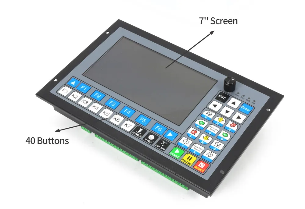
- ♞【Product】Model Number:DDCS EXPERT ; 1M Hz output frequency for each axis; 7 inch full color display screen; resolution ratio: 1024*600, 40 operation keys
- ♞【Introduction】The DDCS Expert numerical control system adopts the ARM+FPGA design framework. ARM controls the human-computer interface and code analysis and the FPGA provides the underlying algorithms and creates the control pulse. This guarantees reliable control and easy operation.The internal operating system is Linux based.
- ♞【Compatible G Code】Compatible with standard G-code,support popular CAD/CAM software, such as ArtCam, MasterCam, ProE, JDSoft SurfMill, Aspire, Fusion 360 and so on;
- ♞【Power Supply】The Power Supply for the controller is 24VDC, minimum Current is 0.5A
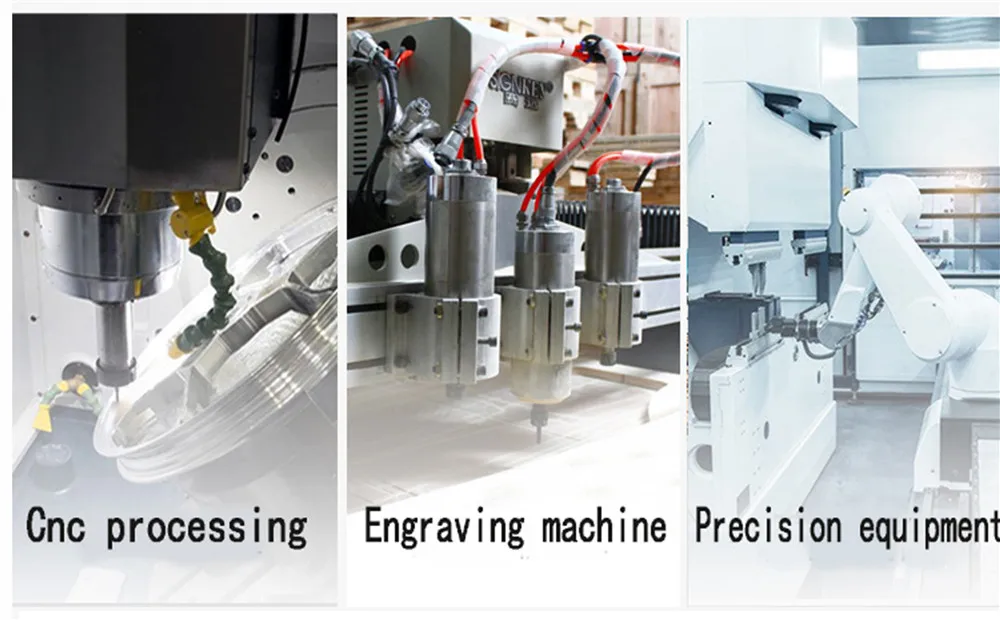
- ♞【Applications】The DDCS Expert can be used for many styles and types of CNC machines. Lathes, CNC Routers,Pick&Place and Milling Machine, lathe and cutters are just a few examples.

DDCS-Expert Brief technical feature:
Introduction
- The DDCS Expert is a 4 axis motion controller for open or close stepper and servo systems with 7/10.2 full color display screen. The highest output pulse per axis is 1MHz. The users can self-define the functional keys. This controller supports multiple spindle mode, support straight Tool Magazine, gantry type Magazine, disk type magazine. The Operation system interface even though very comprehensive, can be learned in very short time.
- The DDCS Expert numerical control system adopts the ARM+FPGA design framework. ARM controls the human-computer interface and code analysis and the FPGA provides the underlying algorithms and creates the control pulse. This guarantees reliable control and easy operation.
- The internal operating system is Linux based.
- The DDCS Expert can be used for many styles and types of CNC machines. Lathes, Routers, Pick&Place and Mills, lathe and cutters are just a few examples. The DDCS Expert operates as a Stand Alone system without the need of a computer. This guarantees high precision, accuracy and reliability.

- The DDCS-Expert is a small box that can fit in a window of a small control box or control cabinet. Four locking hooks fix this controller from the frame. The dimension you find in above figure.
- The front panel is 268mm*172.5mm*5.2mm;
- The main body is 268mm*172.5mm*70mm;
- To mount the unit in an equipment cabinet,cut the hole 258.4mm*109mm
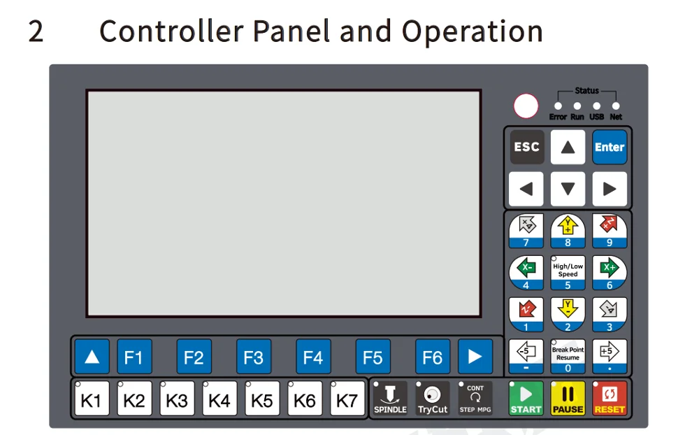
- The front panel consists of 40 user keys and the 7 inch (1024*600) LCD

 Needs two power supplies
- DDCS-Expert needs two power supplies,Main power is for controller system,IO Port power is for Input and Output and MPG ports. Both power supply is 24VDC,current is 3A.In the System Power input port ,the marked 24V and GND is the main power input ports;
- In the IO power input ports,the COM+ and COM- is the power input ports for Input/Output Port and MPG.Please keep in mind,only when the two power supplies are connected correctly the controller can be work properly.
- Many new users only give system power,then the limited switches,the relay,and MPG and spindle don’t work at all,then please go to check if you also give power to IO ports.IO power gives the power to all the IO ports,include the Limited switch,Relay,MPG,Etop and all other Input and output Ports,without it,spindle,MPG,Input and Output ports cannot work.
- In order to avoid electrical noise it is highly recommended to use two separate 24V power supplies.
- In order to avoid high-frequency electrical noise from power supply cable,it is highly recommended to intall a noise filter at the power input to the switch power supply.
|
|
|
|---|---|---|
Size
| Needs two power supplies
| Probe wiring
|


|
|
|
|---|---|---|
Stepper /Servo Driver Wiring
XP+: Pulse Signal Positive Output of the X Axis (5V) XP-: Pulse Signal Negative Output of the X Axis (5V) XD+: Direction Signal Positive Output of the X Axis (5V) XD-: Direction Signal Negative Output of the X Axis (5V) | Limit switch, Home switch and Probe Inputs
| External Buttons
|


|
|
|
|---|---|---|
Relay Wiring
If Relay Power Supply is 24VDC:
If Relay Power Supply is not 24VDC:
| The Wiring for the Multi-Speed Spindle
| Spindle Wiring
|


Functional/Performance comparison between DDCS-Expert and DDCSV3.1
 Wiring diagram

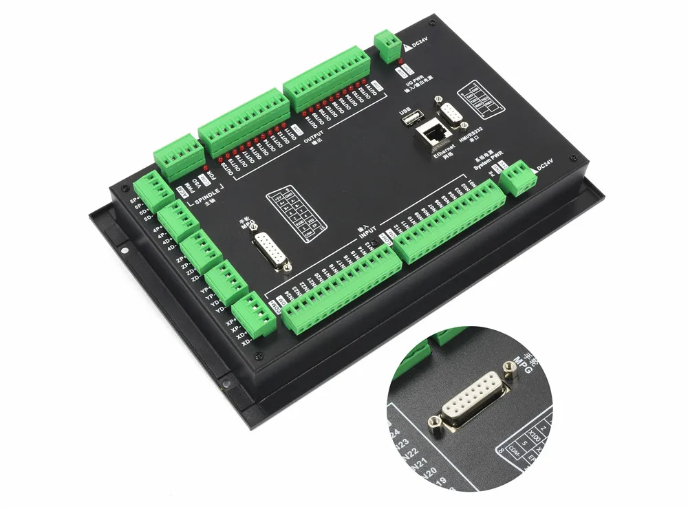
DDCS-Expert wiring board, there are about 7 parts as following:
1) System Power and IO Power supply input Ports;
2) Driver Signal output Ports;
3) Input and Output Ports;
4) Spindle Output Ports;
5) MPG Port;
6) Ethernet and USB interface;
7) HMI/RS232 interface.
|
|
|
|---|---|---|
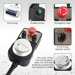
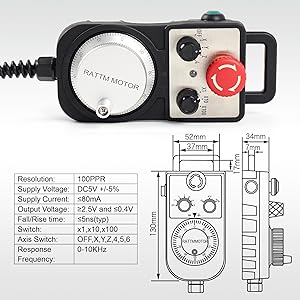
Comes with 4 Axis MPG
| Features of the MPG
| Plug & PlayIn order to make the convenient for the users, we already solder the MPG cables to the PIN15 male interface plug,so that you can plug the MPG to the controller directly.
|


Specifications
- Output voltage: 24VDC
- Rated Current: 3.2A
- Rated Power: 76.8W
- Voltage accuracy: ±1.0%
- Line regulation rate: ±0.5%
- Load regulation rate: ±0.5%
- Working current: 1.4A/115V;0.85A/230V
- Efficiency: 90%
- AC input 115V/230V AC selected by switch; Input voltage: 100-240V AC; Output voltage: 24V; The built-in potentiometer can adjust the output voltage by ± 10%.
Shipping
Please open the package and check if there are some damages before sign,if there are some damages,please do not sign and contact us immediately.
Problem&Feedback
Please give us the opportunityto resolve any problem when you have,we concern your problem and we will try our best to resolve it.
Pls contact us before you want to leave any negative feedback.
Refund
Any reason required for all refund. Item must be in it's original condition and no physical damage,buyer responsible for all shipping cost.
When you have the parcel,and not satisfied the goods or it is other problem like as broken,pls tell us the detail reason and provide the photos.