THORLABS - Ø1" Linear Polarizer with N-BK7 Windows, 400-700 nm (LPVISE100-A)
- The extinction ratio (ER) is the ratio of maximum to minimum transmission of a sufficiently linearly polarized input. When the transmission axis and input polarization are parallel, the transmission is at its maximum; rotate the polarizer by 90° for minimum transmission.
- The extinction ratio is specified at 0º AOI and will vary slightly over the acceptance angle of the optic.
- The power density of your beam should be calculated in terms of W/cm. For an explanation of why the linear power density provides the best metric for long pulse and CW sources, please see the Damage Thresholds tab.

Click to Enlarge
Click Here for Data
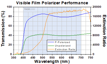
The graph above shows the measured transmission of unpolarized light as well as that of polarized light aligned with the polarization axis of the optic. The shaded region represents the specified operating wavelength range of the polarizer.
These thin film polarizers, which are optimized for use in the 400 - 700 nm range, have an AR coating for the 350 - 700 nm range deposited on the air-to-glass interface of each window. They offer an average transmission of 38% for unpolarized light over their operating wavelength range. The direction of the output polarization is marked on the edge of each polarizer.