Features:
1, the dual H-bridge;
2, rated 7A / Road
3, optocoupler isolation;
4, undervoltage protection;
5, compact size.
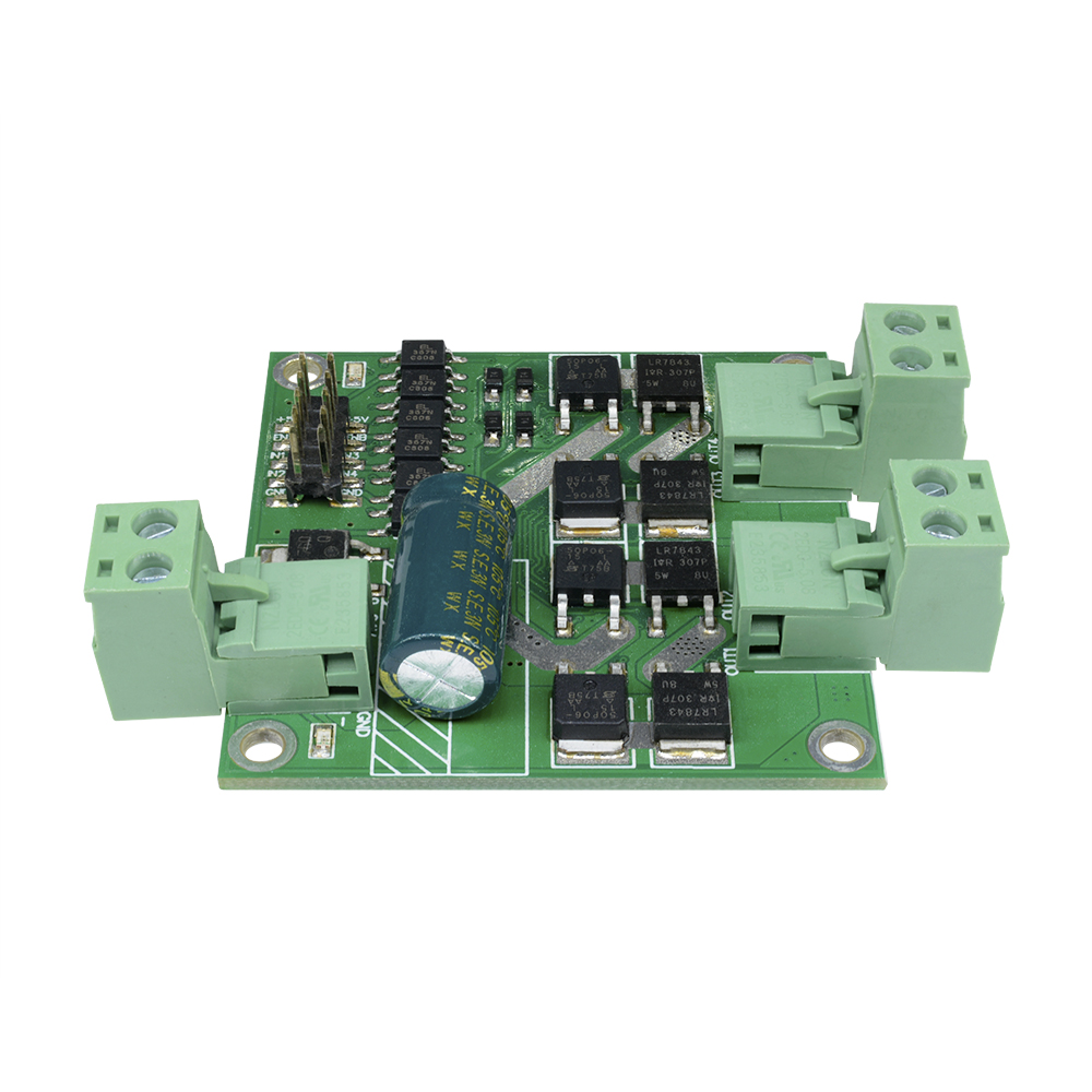
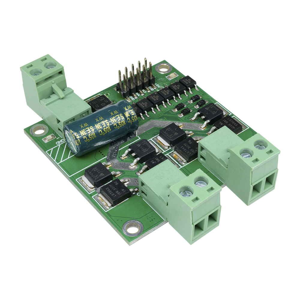
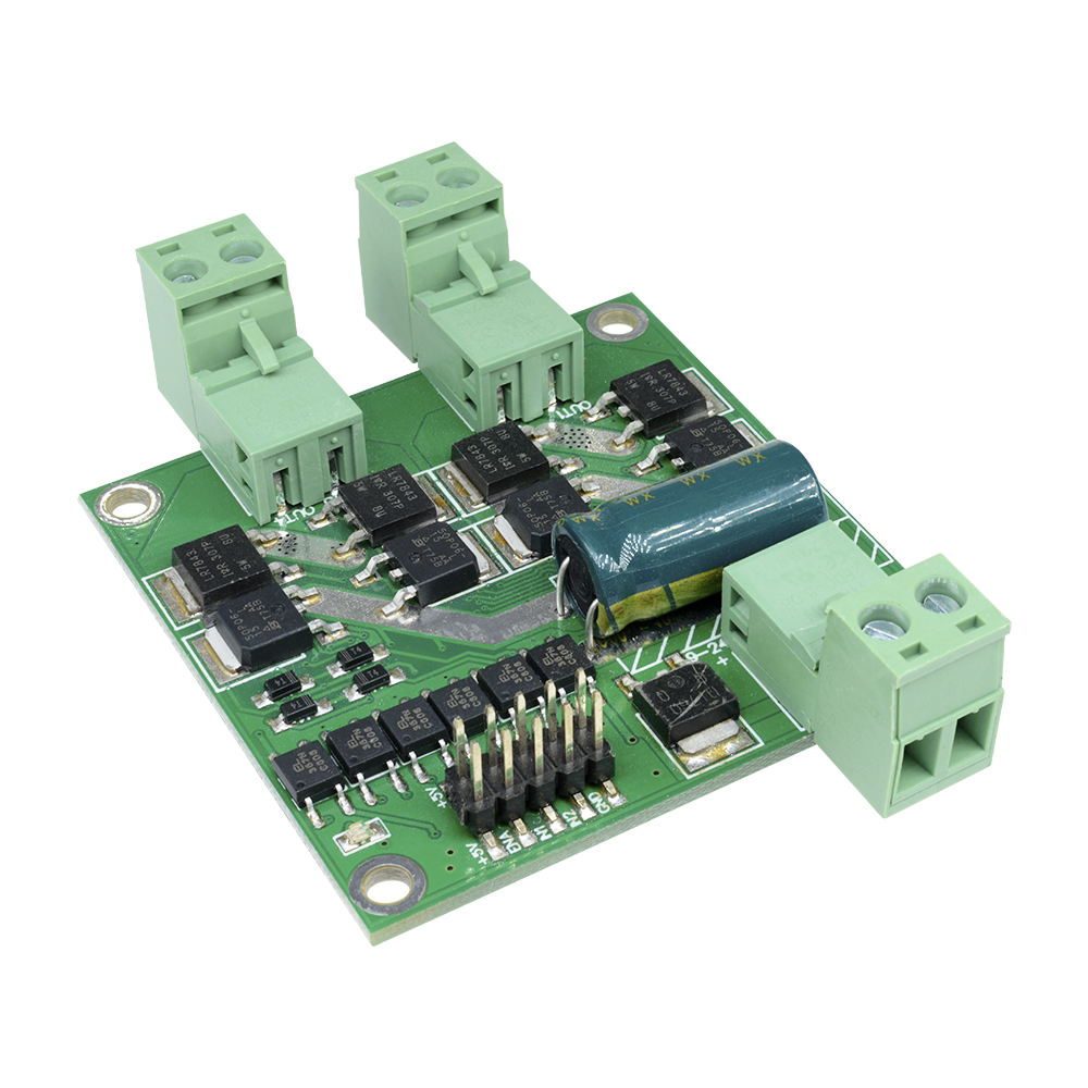
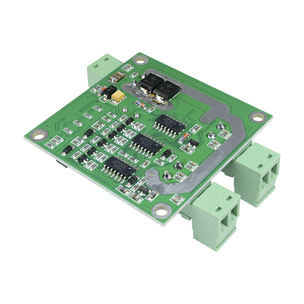
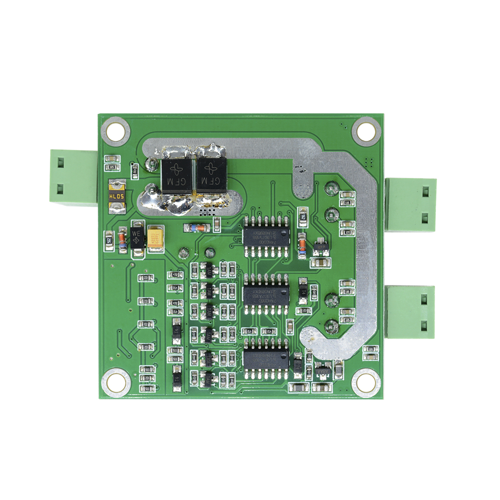
Features:
◆ extremely small size, only 5.5cm × 5.5cm
◆ Support voltage 7V ~ 24V, undervoltage protection
◆ Dual motor interface, each rated output current 7A
◆ L298 similar control logic, each supported by three-wire control is enabled, reversing and braking
◆ enable signal to an external PWM, reversing limit switch control signal can be connected in series
◆ control signal sink drivers, support the vast majority of single-chip direct drive
◆ Use optocoupler isolation for all control signals
◆ electrostatic discharge circuit
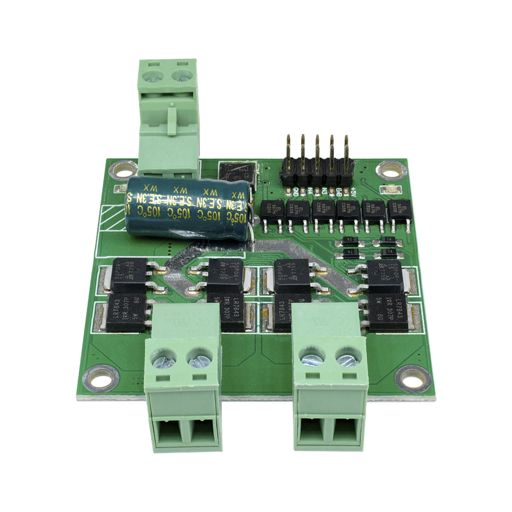
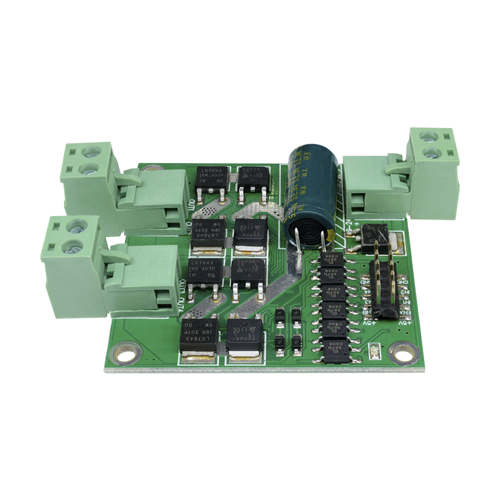
Principle Overview:
The H-bridge module gate circuit, motor reversing combination with MOS transistors, braking and speed control. Both have similar large output current L298 flexible logic control signal.
Interference approach: control signal optocoupler isolation, power spike voltage suppression.
Control signal logic: L298 using gates to achieve a similar control logic.
H-bridge Method: Use P, N complementary MOS transistors to achieve the H-bridge.
Power voltage protection: Use reset chip undervoltage protection.
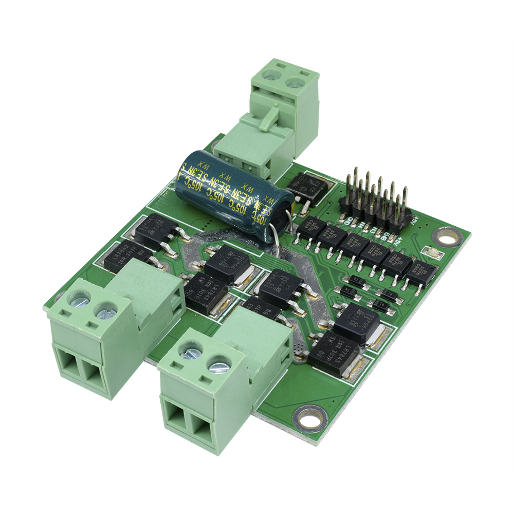
Technical parameters:
Input voltage range: DC 6.5V ~ 27V
Rated input voltage: DC 12V / 24V
Output channels: 2-way
Rated output current per channel: 7A
Peak output current per channel: 50A
Each rated output power: 84W (12V supply) 168W (24V power supply)
The control signal voltage: 3 ~ 6.5V
Each control signal current: 3 ~ 11mA
The minimum effective PWM pulse width: 5us
Working temperature: -25 ℃ ~ 80 ℃
Dimensions: 5.5cm × 5.5cm × 2.0cm
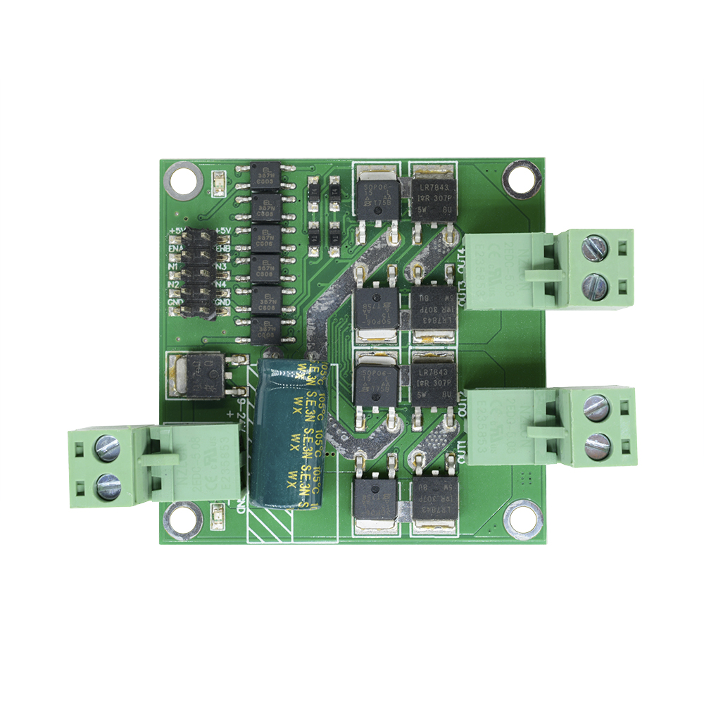
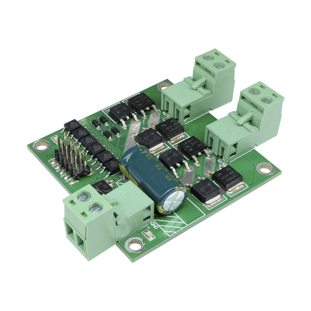
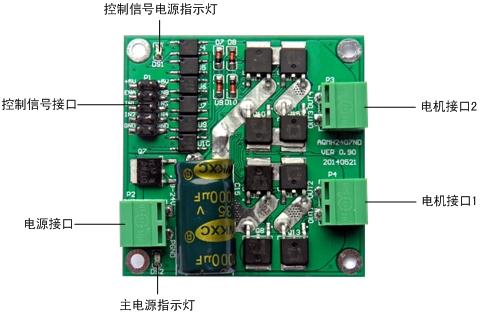
接口定义
Control signal logic
1. The motor control signal interface logic
| IN1 | IN2 | ENA | OUT1、OUT2output |
| 0 | 0 | × | Brakes |
| 1 | 1 | × | Vacant |
| 1 | 0 | PWM |
PWM
Forward Speed
|
| 0 | 1 | PWM |
PWM
Reverse Speed
|
| 1 | 0 | 1 | full forward |
| 0 | 1 | 1 | Full reversal |
Note: The input signal float high
2. The motor control signal interface logic
| IN3 | IN4 | ENB | OUT3、OUT4output |
| 0 | 0 | × | Brakes |
| 1 | 1 | × | Vacant |
| 1 | 0 | PWM | Forward Speed |
| 0 | 1 | PWM |
PWM
Reverse Speed
|
| 1 | 0 | 1 | Full Forward |
| 0 | 1 | 1 | Full reversal |
Note: The input signal float high
A typical example of connection
1. MCU control motor rotation Wiring
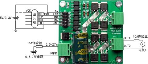
MCU power supply and driver board control signal power should be common ground, but not with the motor power supply GND common ground.
When using a 5V microcontroller, driver board + 5V power supply is + 5V; when using 3.3V microcontroller, driver board + 5V power supply is 3.3V.
Microcontroller and driver board control signal can share a power supply or a separate power supply (but be sure to common ground).
ENA is with a microcontroller GPIO or PWM output port is connected, when ENA is high, the driver board is enabled, reversing or brake effective, if it is a PWM signal, then the motor speed can be; low, driving board is disabled, no output electrical interface.
IN1 and IN2 two GPIO connected with the microcontroller (MCU can support any IO port 51, no pull-up resistor), control motor reversing and braking, drive logic on logic table.
2. Use the buttons to control the motor reversing wiring methods
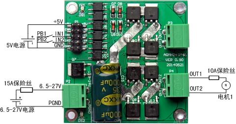
Which, PB1 and PB2 for two keys.
When pressed while PB1 PB2 is not pressed, IN1 is high, IN2 is low, the motor is transferred; when pressed while PB1 PB2 is not pressed, IN1 is low, IN2 is high, motor reverse; when PB1 and PB2 are depressed or have bounce, IN2 and IN2 are low or high, the motor brake (or brake).
See the logic control signal logic table.
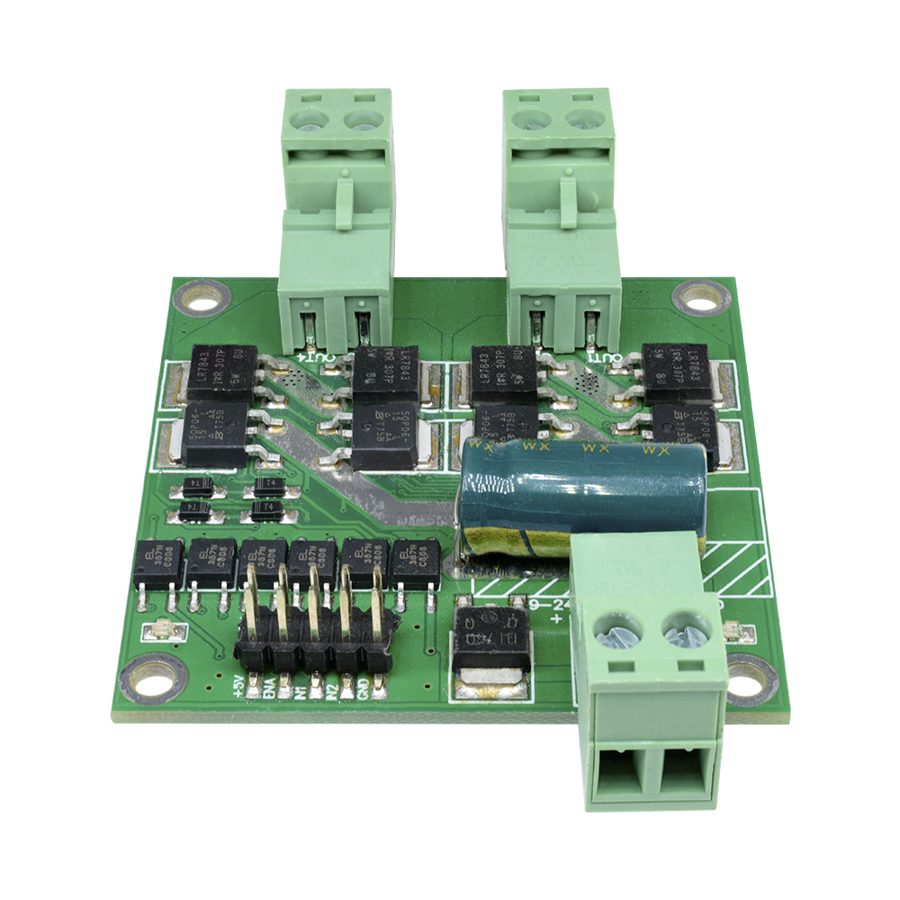
Size definition
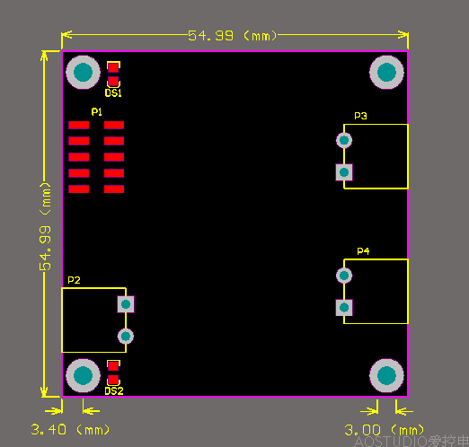
Size of 5.5cm × 5.5cm × 2.0cm. Installation hole diameter is 3mm, suggested the use of M3 screws to fix.
Note that when you install, do not let the back of a short circuit, you can add insulation pad or use Tongzhu raise the board.
Package Included:
1 x 12V/24V 7A 160W *2 L298 H-bridge DC Motor Drive Module