
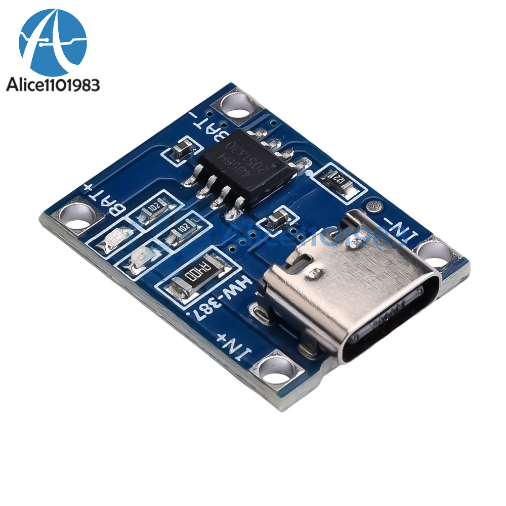

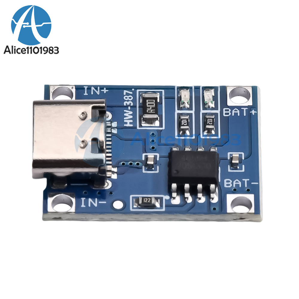
Product Details
Micro USB interface:
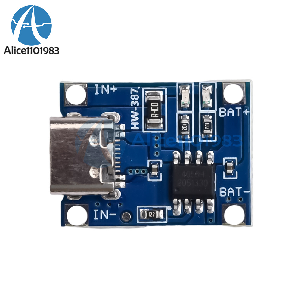
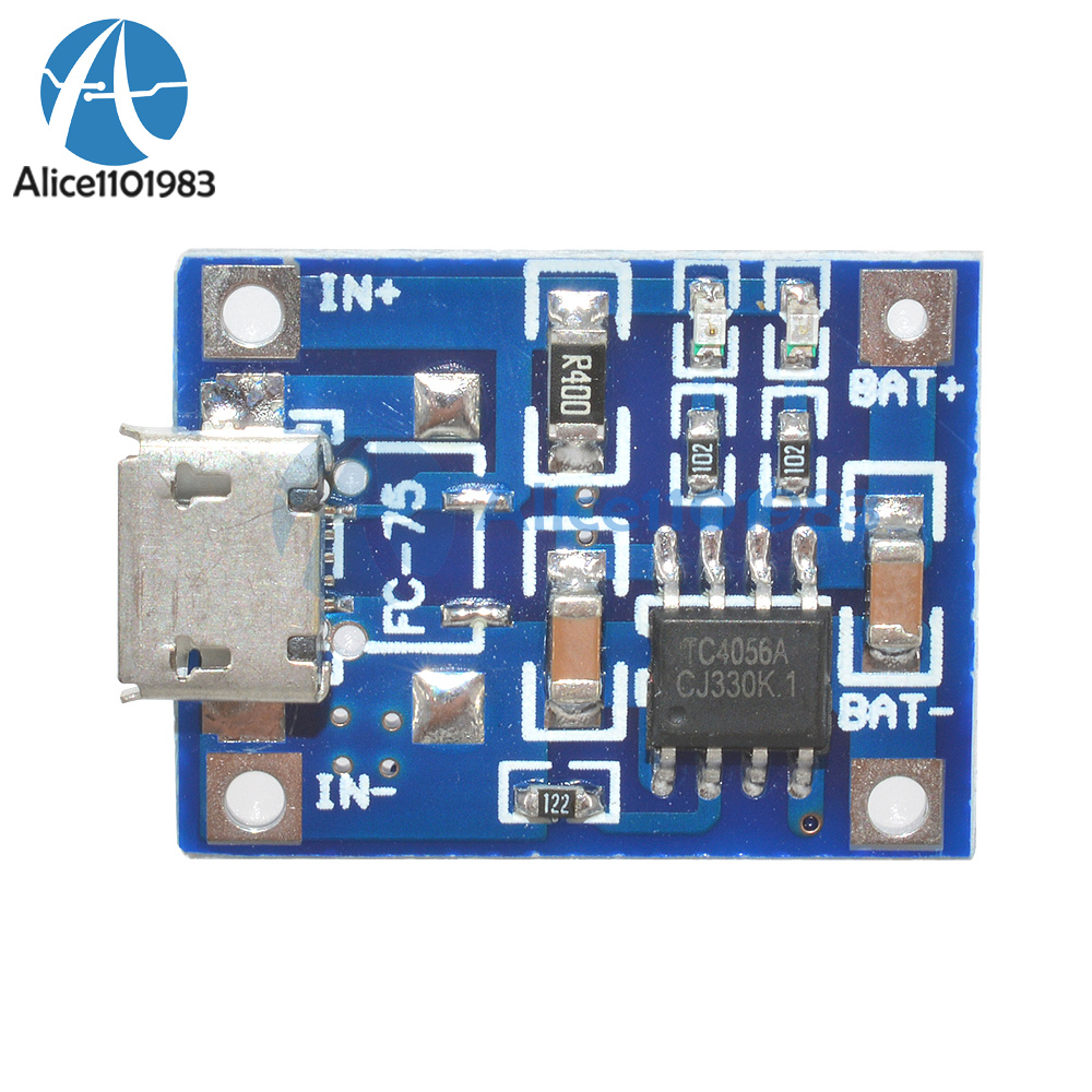
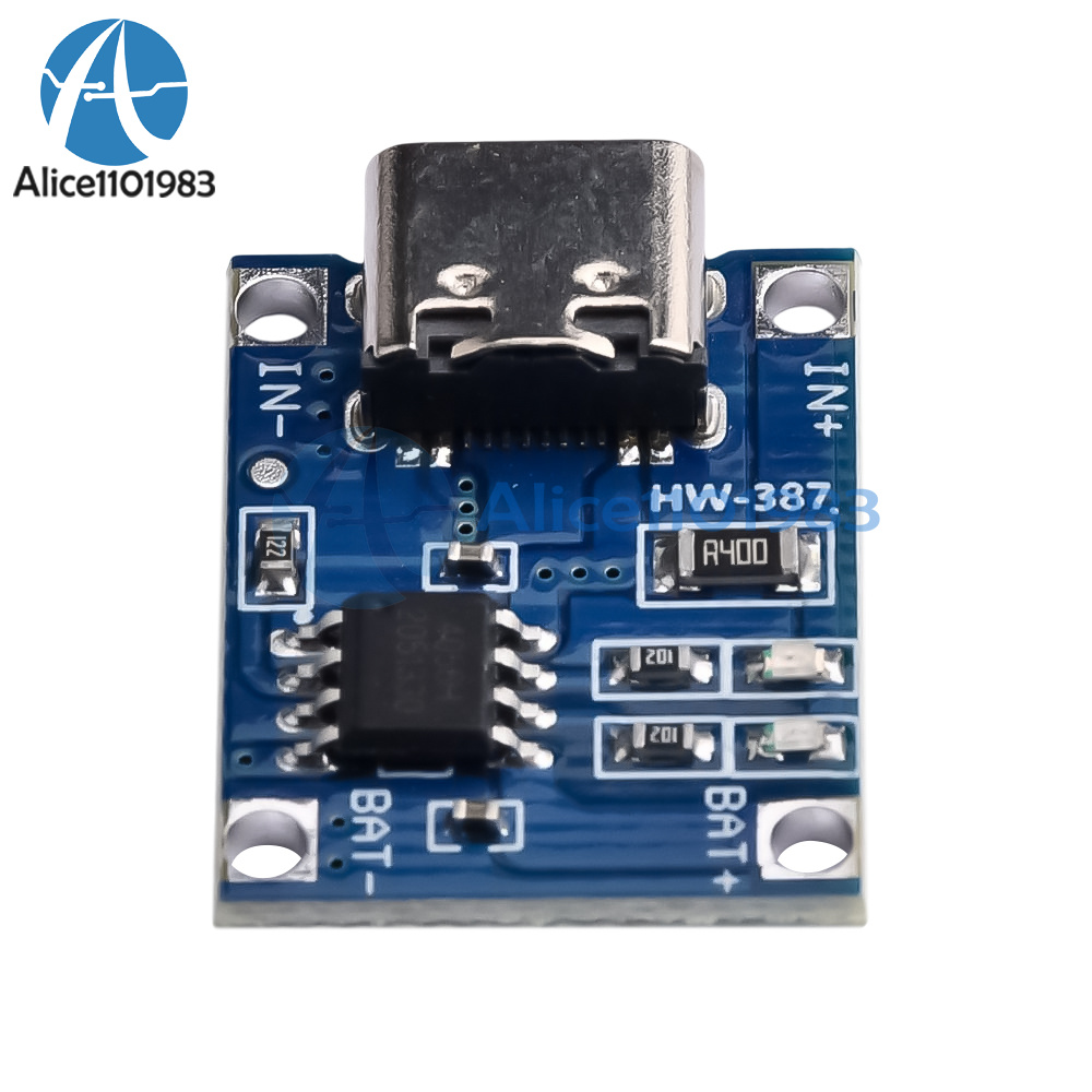
Module features and parameters
Input voltage: 5V
Charging cut-off voltage: 4.2V min 1%
Maximum charging current: 1000mA
Battery over discharge protection voltage: 2.5V
Battery overcurrent protection current:3A
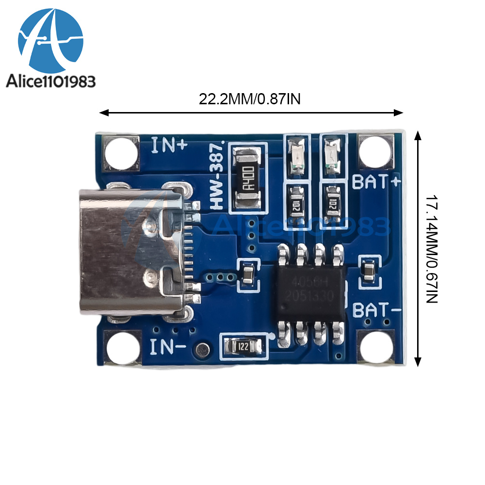
Board size:2.6*1.7CM
Can be used for voltage 3.6 3.7V 18650, polymer lithium batteries such as charge and discharge protection, single or multiple parallel can also be used
Note: The first time you access the battery, there may be no voltage output between OUT+ and IOUT-, then access the 5V voltage charge can activate the protection circuit.
Battery from the B + B- on the short open and then connected to also need to charge a little to activate the protection circuit.
When using a cell phone charger to do the input, note that the charger must be able to output 1A or more, otherwise it may not be able to charge properly
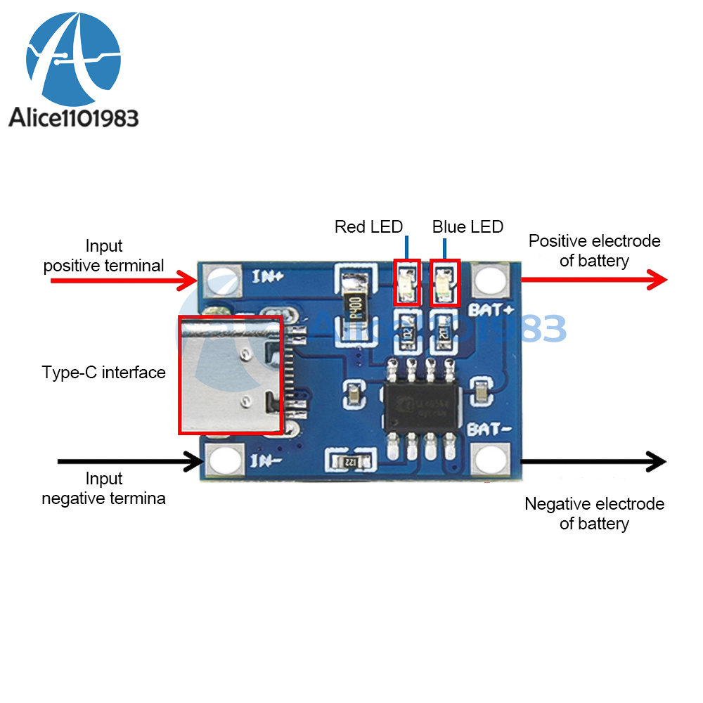
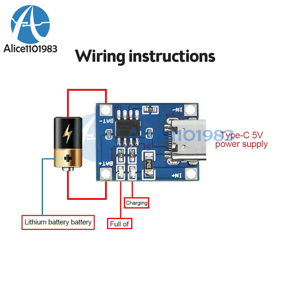
MINI USB female chassis and the +- pad next to the power input, access to 5V. B + connect the positive terminal of the lithium battery, B - connect the negative terminal of the anal battery.
OUT+ and OUT- connected to the load, such as connecting the positive and negative terminals of the mobile boost board or other loads.
Connect the battery to B+ B-, insert the phone charger to the USB female socket, the red light is charging, the green light is full.
Module application range:
This module is used to charge single lithium battery or multiple lithium batteries in parallel, the charging port can take power from USB.
1. The ammeter for testing current can only be connected in series to the 5V input of the charging board.
2. The charging current is preferably 0.37C of the battery capacity, that is, 0.37 times the capacity, for example, 1000mAH battery charging current 400 so it is enough. Too large charging speed fast effect is poor, after charging the battery voltage off more!
3. charging connection wire can not be too thin and too long. This connection resistance is large. Too thin, then the battery voltage will fall off more. 4. and the battery connection is best contact good. Otherwise, the battery voltage will fall off more after charging.
5. If the 5V input voltage is high, such as 5.2 or even 5.5, will cause the charging current is less than 1000mA, which is normal. High voltage chip heating will automatically reduce the charging current, not to the chip burned. Chip in the work of about 60 degrees heat is normal. After all, the charging current is high.
6. input reverse connection on the chip does not affect, but the output (battery side) reverse connection will burn the chip, please pay attention to buyers.
Product parameters:
Input voltage: DC4.5V - 5.5V;
IN+ IN- pad wiring or Type-C 5V input;
Charging as of voltage: DC4.2V;
Charging current: 1A adjustable;
with charging indicator;
Operating temperature: -10°C to +85°C;
1. Pay attention to the wiring according to the diagram, do not connect the wrong.
2. This document only represents the editor's knowledge and parameters of the product at the time, and any later changes without notice.
3. charging needs to be connected with a short and thick wire, too thin and too long, the connection resistance is large, after charging, the battery voltage dropped more.
4. Connect the wires, need to contact well, otherwise after charging, the battery voltage will drop more;
5. If the 5V input voltage is high, such as 5.2V or 5.5V, it will cause the charging current to be less than 1000mA, which is normal. High voltage chip heating, will automatically reduce the charging current, reducing the chances of the chip being burned.
6. Charging current is too large, or in a high temperature environment, the need to do heat dissipation treatment.
7. The ammeter for testing current can only be connected in series with the 5V input of the charging board.
8. The satisfactory effect of charging current should be 0.37 times of the battery capacity. For example, 1000mAH battery charging current 400mA is fine.
9. The charging speed is fast, the charging effect is poor, and the more the battery voltage drops after charging is completed.
After power-up, the module's blue indicator light is always on and the red indicator light is faintly flashing;
When fully charged to the battery, the module's blue indicator light is always on;
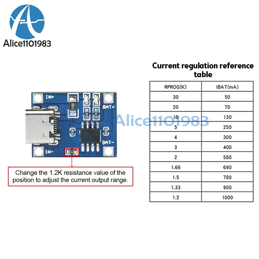
Description of current adjustment:
Output current can be adjusted by itself, change the fixed resistor in the circuit board, you can change the output current of 100mA ~ 1000mA
5/10 PCS module
- EBAY Managed Payment. But we only Accept your Ebay Address, please Make sure it's 100% right.
- Payment must be received in 5 business days of auction closing.
- Please leave note for your special request (e.g. Colors or Size) in PayPal when you pay the order.
- Any special request cannot be accepted after 24 hours of payment, because most of orders will be processed instantly and same day dispatched.
1. We only ship to the confirmed address provided by eBay. please make sure your ebay address is 100% matches the address you would like us to ship to. If not, please let us know before we sent you the package, or we will not be responsible for any loss. hope you could understand.
2. Orders will be processed instantly and dispatched within 1-3 business days except hoilday, so we do NOT accept any email/message note after you place orders.
3. All package need to wait 30 days,Please take care it.Less than 30 days,we can't take a refund.
- All package need to wait 30 days(US only need 7-10 days),Please take care it.Less than 30 days,we can't take a refund.
- If the item is defect when you receive it or you are not satisfied with it, please return it within 14 days for a replacement or money back. But the items must be back in factory condition. Please keep in touch with us and double check the return address before you return it.
- If is item is defective in 12 months, you can return it to us. We will send you a new replacement after receiving the defective item.
We maintain high standards of excellence and strive for 100% customer satisfaction! Feedback is very important to us. We request that you keep in touch with us immediately BEFORE you give us neutral or negative feedback, so that we can satisfactorily address your concerns.