


18 -> DS2482-100 20 -> MCP23008 48 -> TMP102 50 -> 24c32
68 -> RTC DS1307 60 -> MCP4725 49 -> ADS1015


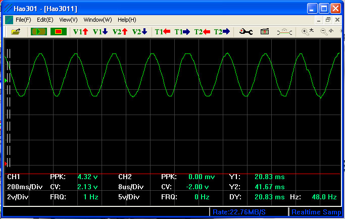

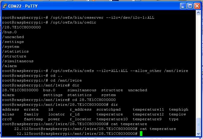
/28.7E1CC8030000 - Connect & Detect DALLAS 18B20P TEMP Sensor
cat temperature -- 22.312 & 32.125
3. U7 TMP102 Temperature Sensor
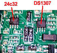
4. U9 24C32 32Kbit EEPROM
5. U6 MCP4725 12bit Digital-to-Analog Converter
JP11 (AOUT, GND) JP1 Disable Jumper
6. U11 ADS1015 12bit Analog-to-Digital Converter ,
J7 INPUT (AIN0, AIN1,AIN2,AIN3,GND,3V3) JP12 Disable Jumper
7, J5 (5V, GND,SCL,SDL) J6(3v3,GND,SCL,SDL) I2C output
8. U2 - USB 4 Ports HUB chipset
J1 (JP3) USB HUB upper port signal input from Rs-Pi
9. J13 Mini USB 5V input for USB HUB, you don't need plug 5V , the HUB already use 5V from Raspberry Pi,
if your use USB device need more power, then you can plug-in 5V in this port.
10. U15 DS2482-100 I2C to 1-Wire bridge device
J22 1-wire Port pin 1 - pin4
(5V,GND, OW (1-Wire Data, ESD Protected). RT (1-Wire Return/Ground ,ESC protected
11. U16 DS9503P 1-Wire ESD protection diode
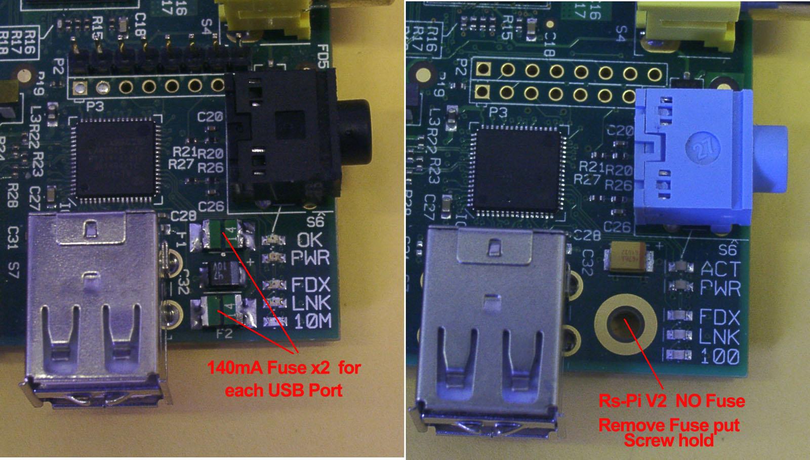
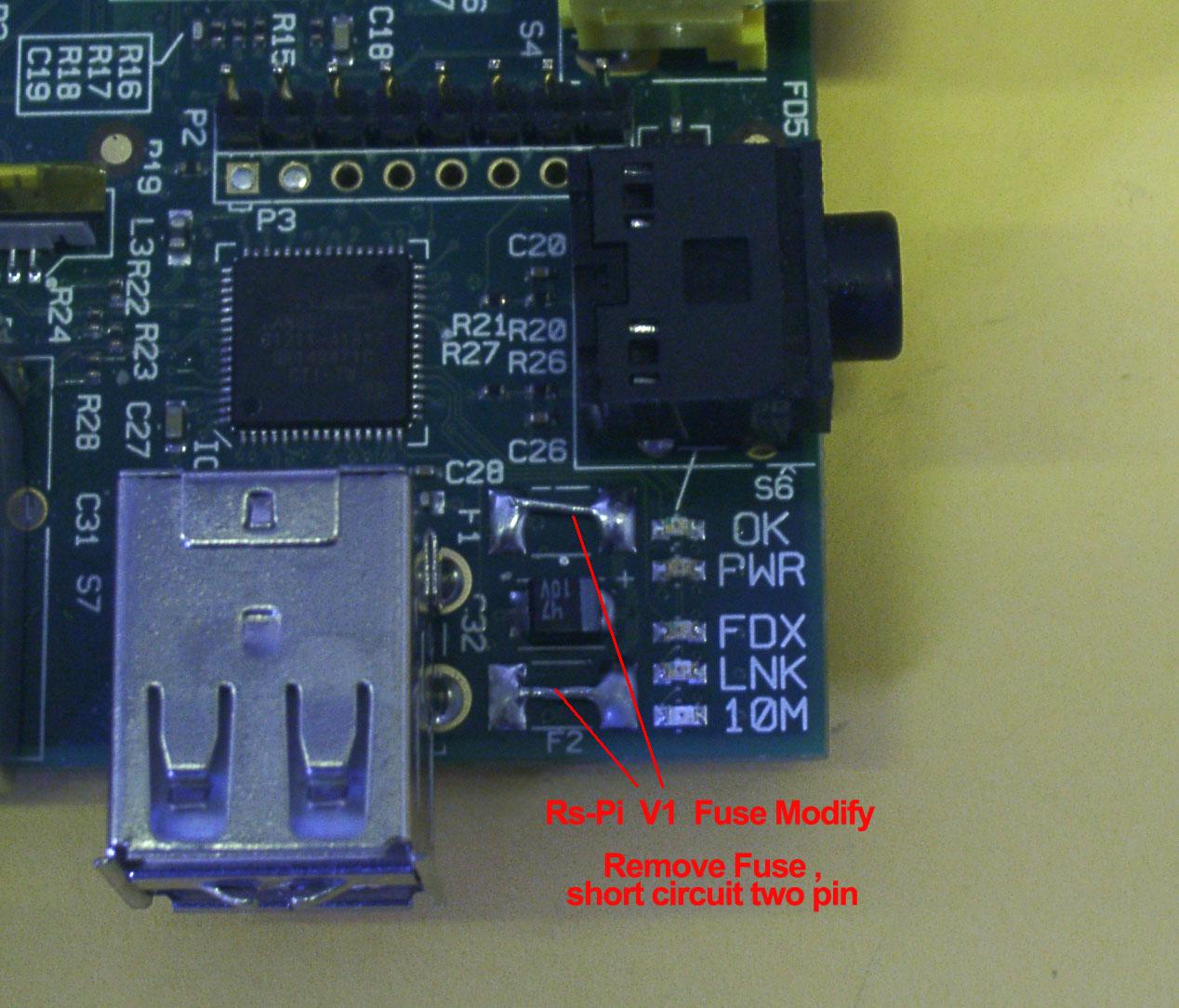
To keep Rs-Pi USB Hub board working properly, you need keep the Vcc input for Rs-Pi above 4.75V,
JP3 pin 1 Vcc, pin4 GND
|
Adafruit
Occidentalis v0.2
image support the TMP102 , RTC DS1307 , ADS1015 and MCP4725 Use this board you can learn how to program use "C" or "Python" , Will provide sample program for test can download from our web site. | |||
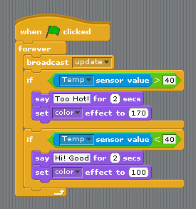
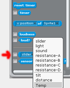
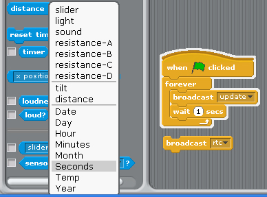
Full Support by our Pi_Scratch software can be very easy control by Scratch Pi_Scratch detail Scratch driver software (1) i2c address 48 TMP102 temperature sensor test
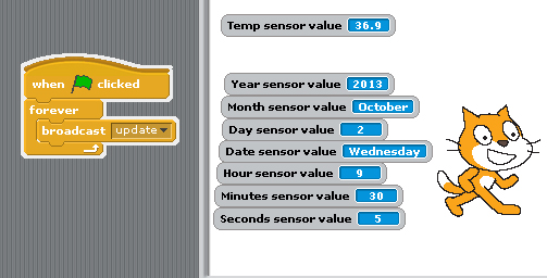
after broadcast "Update" in Sensing --> Slider , you will see the Temp in the list
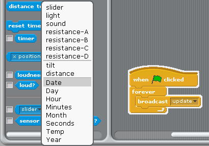
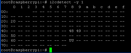
(2) i2c address 68 DS1307 RTC detect & demo
after broadcast "Update" in Sensing --> Slider , you will see the RTC in the list "Year, Month, Day, Date, Hour, Minutes, seconds"
RTC information from Raspberry Pi i2c RTC module
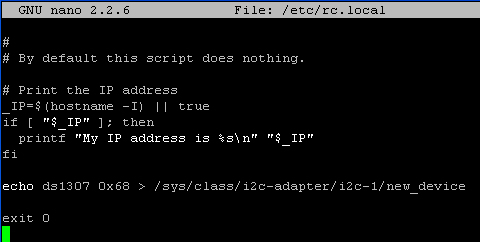
if you can't detect RTC function in Scratch
you have echo ds1307 in /etc/rc.local
in 0x68 address display "UU"
send broadcast"rtc" then broadcast"update" after broadcast "Update" in Sensing --> Slider , you will see the RTC in the list "Year, Month, Day, Date, Hour, Minutes, seconds" (3) i2c address 20 23008 8 GPIO test
use command 8pin+"address"+a"bit (1 to 8)" 8pin+"address"+ a"10001000" --> 8bit mode 8pin20a5 --> output to address 20 bit 5 or use "8pin20a10010011" --> 8bit address 20 from 8 to 1 "10010011"
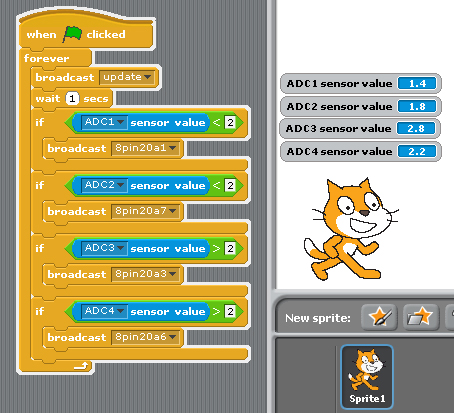
(4) i2c address 49 adc ads1015 4 channel input test i2c adc ads1015 12bit Analog-to-Digital Converter
after broadcast "Update" in Sensing --> Slider , you will see the ADC1, ADC2,ADC3, ADC4 in the list
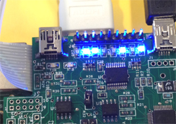
(1)adc1 input & output to 23008 8 bit GPIO bit 1 if adc1 < 2 23008 bit 1 LED "ON" 8pin20a1 (2) adc2 input & output to 23008 8 bit GPIO bit 7 if adc2 < 2 23008 bit 7 LED "ON" 8pin20a7
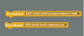
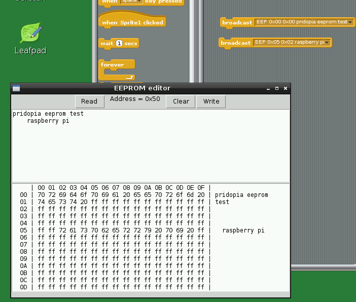
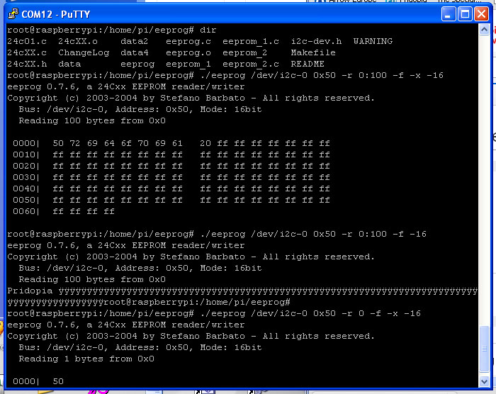
(5) EEPROM i2c address 50 24c32 read/write
command "EEP" + start address x, start address y + " message" --> EEP 0x00 0x00 pridopia eeprom test
The System will open a new screen for EEPROM editor , need waiting about 10 seconds
| |||
1.We accept payment through Paypal ONLY. |