MULTI-
Suitable for single and three phase generators.
PREFACE |
The Model AECM105V is an Automatic Engine Control Module designed to automatically or/and manually start and stop a generator engine. It will indicate the operational status and fault conditions, automatically shut down the engine and indicate the start engine failure by a flashing “START FAIL” LED on the front panel. Other faults are indicated by steady LED.Operation of the module is via 2 position maintained toggle switch [RST] mounted on a wall or any other suitable place with ON-OFF positions (customer supplied part). Wireless control of the module is via key fob [optional]. IMPORTANT! |
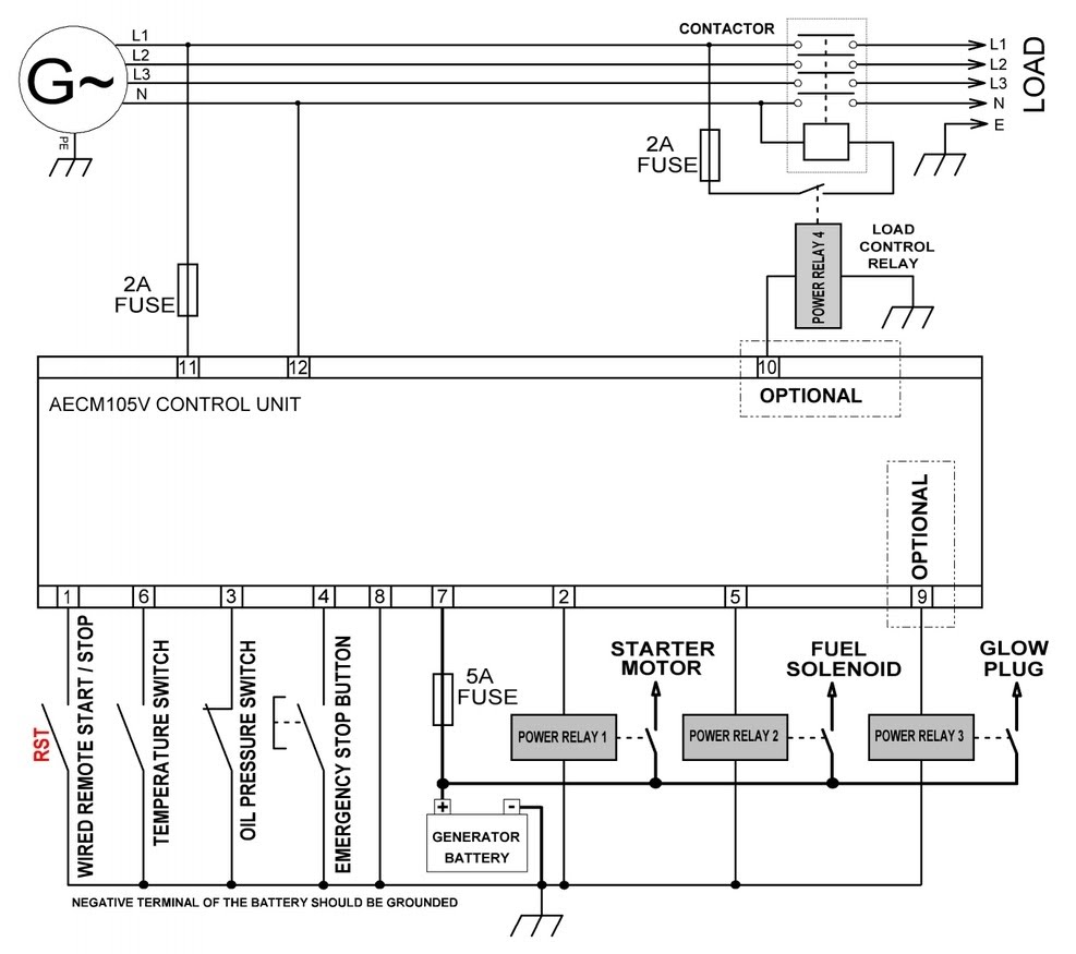
The starter relay [terminal No 2] can only energize for 2 nd and 3 rd crank cycle if “Low Oil Pressure” is sensed [via terminal No 3], to confirm that the engine is stationary. This is designed to prevent damage to the starter and ring gear in the event of the control module not sensing that the engine has started [i.e. AC Alternator is not connected to terminals 11 and 12].
PIN | CONNOTATION | DEFAULT SETTINGS/NOTES |
1 | Remote wired start/stop input | N/O maintained switch |
2 | Starter motor relay output | Batt. pos. output |
3 | Oil pressure switch input | N/C (if engine is not running) |
4 | Emergency stop switch input | N/O type |
5 | Fuel solenoid relay output | Batt. pos. output |
6 | Engine temperature switch input | N/O type |
7 | Battery positive power supply (+) | 6...40Vdc |
8 | Battery negative power supply (–) | Common wire |
9 | Glow plug relay output (optional) | Batt. pos. output |
10 | Load control relay output (optional) | Batt. pos. output |
11 | Generator live input (L) | 100~300Vac |
12 | Generator neutral input (N) | 100~300Vac |
The relays supply positive plant supply out. | ||
AECM105V specification
DC Supply: generator battery 12V or 24V (6...40Vdc)
Max. standby current: 10mA @12Vdc
AC voltage input max: 300Vac
Under speed S/D @ 30Hz (45Hz for USA and Canada)
Over speed S/D @ 57Hz (69Hz for USA and Canada)
Number of attempts: 3 (user-
Crank duration: 12sec (automatically regulated via sensing AC alt.)
Pre-
Load On/Off delay: 60sec (user-
Hold-
Starter / Fuel / Glow / Load relay output: 3.0A max (by-
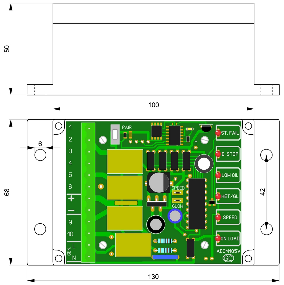
Dimensions: 100x68x50mm
Enclosure type: weatherproof IP67 rated
Operating temperature range: -
Humidity Range Operating: 20-
DESCRIPTION
WIRED REMOTE / LOCAL CONTROL | |
Toggle switch RST is On (closed) | |
0.5 Second after the fuel relay is energized [terminal 5], the 3 attempt start will begin its start sequence: the start relay will energize, feeding battery +ve (on terminal 7 to terminal 2 and thence on to the start circuit. If the engine has not fired by the end of 1st attempt, the starter is turned off for a resting period. The sequence will then repeat up to a maximum number of start attempts. Following a successful start, sensed when AC alternator's voltage rises above 40% of nominal, the start relay is de- | |
PRE- | |
GLOW jumper is fitted | |
10 second after the pre- | |
LOAD CONTROL (optional) | |
After a successful start, when engine's parameters are settled (when time delay provided by hold- | |
WIRELESS CONTROL VIA KEY FOB (optional) | |
Toggle switch RST is Off | |
Make sure there are no metal doors/walls/other metal shields between you and AECM105V module. Any metal/brick wall can significantly reduce the working distance. | |
Wireless transmitter/receiver specification The key fob (transmitter) comes without battery included. Please fit type 23A 12V battery. Need an extra key fob? Please feel free to order one or more from this listing (we will post it together with your AECM controller):https://www.ebay.co.uk/itm/225912375825 | |
RELAY OUTPUTS ARE PROVIDED FOR: | CONFIGURABLE INPUTS ARE AVAILABLE FOR: |
» Starter Motor Output | » Wired remote start/stop |
MULTIPLE ALARM CHANNELS ARE PROVIDED TO MONITOR THE FOLLOWING: | |
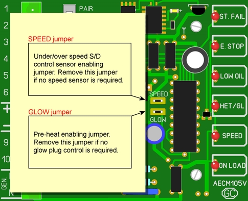
» Under/Over speed S/D (speed fault). This alarm sensor can be enabled/disabled via SPEED jumper. | |
* During engine cranking and for a short time afterwards the protective hold- | |
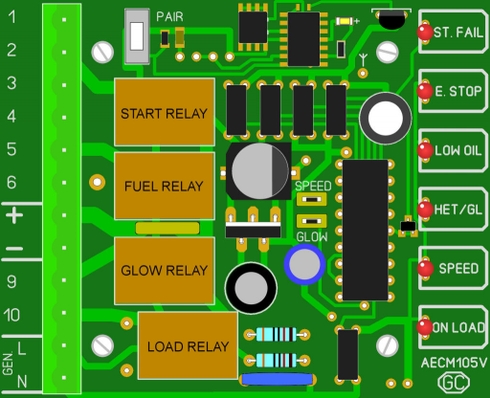
PCB CONFIGURATION