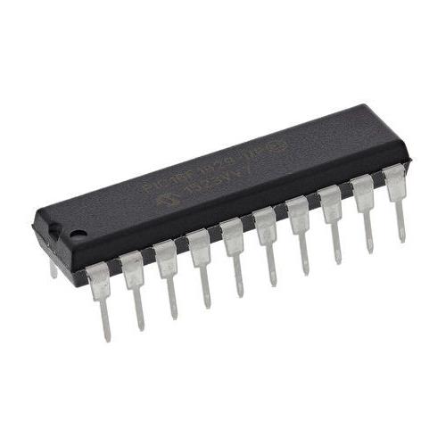


| Product Category: | Digital Signal Processors & Controllers - DSP, DSC | |
| Manufacturer: | Microchip | |
| Product: | DSCs | |
| Core: | dsPIC33FJ | |
| Maximum Clock Frequency: | 40 MHz | |
| Program Memory Size: | 64 kB | |
| Data RAM Size: | 8 kB | |
| Operating Supply Voltage: | 3 V to 3.6 V | |
| Maximum Operating Temperature: | + 85 C | |
| Mounting Style: | SMD/SMT | |
| Package/Case: | TQFP-80 | |
| Packaging: | Tray | |
| Brand: | Microchip Technology | |
| Data Bus Width: | 16 bit | |
| Height: | 1 mm | |
| Instruction Type: | Fixed/Floating Point | |
| Interface Type: | CAN, I2C, SPI, UART | |
| Length: | 12 mm | |
| Minimum Operating Temperature: | - 40 C | |
| Number of I/Os: | 69 I/O | |
| Number of Timers/Counters: | 9 Timer | |
| Processor Series: | dsPIC33F | |
| Program Memory Type: | Flash | |
| Series: | dsPIC33FJXXXMCX08A | |
| Supply Voltage - Min: | 3 V | |
| Width: | 12 mm | |
| Unit Weight: | 513.600 mg |
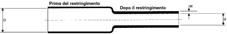
TE Connectivity Black Heat Shrink Tubing, 9.5mm, 2:1, 10m Length
- BMUK Part # :-219-6513
- BrandTE Connectivity
- Mfr. Part No.DR-25-3/8-0-10

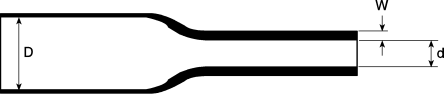
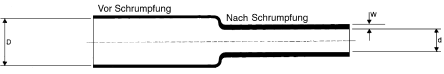
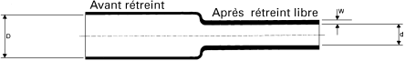
DR-25 Heat shrink Tubing (Shrink Ratio 2:1)
Robust and flexible heat shrink tubing. It protects wires and cables against damage from chemicals, abrasion, and fluids. The tubing is ideal for use in high temperature environments as it has been specially designed for long term heat resistance and is flame retardant.
Features and Benefits
• Offers excellent protection and insulation
• Provides strain relief
• Performs well under long-term heat exposure
• The tubing is printed with the product description and size
• Shrink ratio of 2:1
• Use with System 25 range products for a complete cable harness system
Standards
VG95343 Part 5 Type D, VDE 0341/Pt 9005, AMS-DTL-23053/16, BS36-198 Part 3 10A.
High Temperature
| Sleeve Diameter | 9.5mm | |
| Shrunk Diameter | 4.8mm | |
| Colour | Black | |
| Sleeve Type | Heat Shrink | |
| Shrink Ratio | 2:1 | |
| Sleeve Length | 10m | |
| Material | Elastomer | |
| Minimum Operating Temperature | -75°C | |
| Maximum Operating Temperature | +150°C | |
| Dielectric Strength | 8kV/mm |
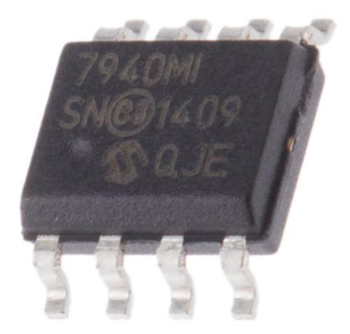
Microchip MCP7940M-I/SN Real Time Clock — Calendar, NV SRAM, 64B RAM 8-Pin SOIC
- BMUK Part # :-761-7627
- BrandMicrochip
- Mfr. Part No.MCP7940M-I/SN

MCP7940M I²C Real-Time Clock/Calendars
The Microchip MCP7940M is Real-Time Clock Calendar (RTCC) that supports I²C communications. The MCP7940M includes a digital trimming circuit for accuracy which can compensate for crystal tolerance and temperature.
The MCP7940M features a multi-functional output that can be configured as an alarm output, to output a selectable frequency square wave or as a general purpose output.
Features
2-Wire Serial Interface, I²C™ Compatible: I²C clock rate up to 400 kHzOn-Chip Digital Trimming/Calibration: ±1 ppm resolution, ±129 ppm range
Tracks Hours, Minutes, Seconds, Day of Week, Day, Month and Year
Leap Year Compensated to 2399
12/24 Hour Modes
Oscillator for 32.768 kHz Crystals: Optimised for 6-9 pF crystals
Dual Programmable Alarms
Versatile Output Pin
Wide Operating Voltage Range: 1.8V to 5.5V
Low Typical Timekeeping Current: 1.2μA at 3.3V
Real Time Clock Peripherals - Microchip
| Functions | Calendar, NV SRAM | |
| Date Format | DW:DM:M:Y | |
| Time Format | HH:MM:SS | |
| User RAM | 64B | |
| Bus Type | Serial-I2C | |
| Mounting Type | Surface Mount | |
| Package Type | SOIC | |
| Pin Count | 8 | |
| Dimensions | 4.9 x 3.9 x 1.25mm | |
| Length | 4.9mm | |
| Width | 3.9mm | |
| Height | 1.25mm | |
| Maximum Operating Supply Voltage | 5.5 V | |
| Minimum Operating Supply Voltage | 1.8 V | |
| Maximum Operating Temperature | +85 °C | |
| Minimum Operating Temperature | -40 °C |
Microchip BLDC Motor for MCP8024 Demonstration Board
- BMUK Part # :-893-8149
- BrandMicrochip
- Mfr. Part No.ADM00557

MCP8024 BLDC Motor Driver Evaluation Board
The MCP8024 Evaluation Board is a platform which demonstrates Microchip’s MCP8024 3-Phase Brushless DC (BLDC) Gate Driver in a BLDC motor drive application. The featured device integrates three Half-Bridge Drivers to drive external NMOS/NMOS transistor pairs, a comparator, a voltage regulator, power monitoring comparators, an over-temperature sensor, two level translators and three operational amplifiers into one IC.
The evaluation board allows designers to quickly and easily start assessing the device and includes a start-stop pushbutton and motor speed controlling potentiometer on board. To implement the demonstrated trapezoidal BLDC Motor Controller solution the MCP8024 is used in combination with a companion Digital Signal Controller, Microchip’s dsPIC33FJ32MC204, which is present in Plug-In Module form.
Features
Input Operating Voltage Range: +7.0V to +28VMaximum of 500 mA of gate drive current for external N-Channel MOSFETs
Drives a BLDC motor with a supply of up to 28V and 15A
750 mW Buck Regulator with resistor programmable output voltage
RESET momentary contact switch
Two Spare user programmable momentary contact switches
PWM signal LED indicators
100 pin dsPIC PIM header for use with MA330017 compatible PIMs
PICkit 3, Real Ice and ICD3 debugger interfaces
Speed control potentiometer
Terminal block for 5V or 12V Hall effect sensors
SPI and I2C headers for user communications use
Programmable external MOSFET overcurrent protection
Programmable PWM dead-time protection
Programmable PWM blanking time for current switching spikes
On-board 5V and 12V LDO regulators
Kit Contents
1 x MCP8024 TQFP BLDC Motor Driver Evaluation Board1 x dsPIC33FJ32MC204 Plug-In-Module (MA330017)
Note
BLDC motor is not included
Motor Controllers & Drivers, Microchip
| Power Management Function | BLDC Motor | |
| Kit Classification | Demonstration Board | |
| Featured Device | MCP8024 | |
Microchip BLDC Motor for MCP8024 Demonstration Board
- BMUK Part # :-893-8149
- BrandMicrochip
- Mfr. Part No.ADM00557
MCP8024 BLDC Motor Driver Evaluation Board
The MCP8024 Evaluation Board is a platform which demonstrates Microchip’s MCP8024 3-Phase Brushless DC (BLDC) Gate Driver in a BLDC motor drive application. The featured device integrates three Half-Bridge Drivers to drive external NMOS/NMOS transistor pairs, a comparator, a voltage regulator, power monitoring comparators, an over-temperature sensor, two level translators and three operational amplifiers into one IC.
The evaluation board allows designers to quickly and easily start assessing the device and includes a start-stop pushbutton and motor speed controlling potentiometer on board. To implement the demonstrated trapezoidal BLDC Motor Controller solution the MCP8024 is used in combination with a companion Digital Signal Controller, Microchip’s dsPIC33FJ32MC204, which is present in Plug-In Module form.
Features
Input Operating Voltage Range: +7.0V to +28VMaximum of 500 mA of gate drive current for external N-Channel MOSFETs
Drives a BLDC motor with a supply of up to 28V and 15A
750 mW Buck Regulator with resistor programmable output voltage
RESET momentary contact switch
Two Spare user programmable momentary contact switches
PWM signal LED indicators
100 pin dsPIC PIM header for use with MA330017 compatible PIMs
PICkit 3, Real Ice and ICD3 debugger interfaces
Speed control potentiometer
Terminal block for 5V or 12V Hall effect sensors
SPI and I2C headers for user communications use
Programmable external MOSFET overcurrent protection
Programmable PWM dead-time protection
Programmable PWM blanking time for current switching spikes
On-board 5V and 12V LDO regulators
Kit Contents
1 x MCP8024 TQFP BLDC Motor Driver Evaluation Board1 x dsPIC33FJ32MC204 Plug-In-Module (MA330017)
Note
BLDC motor is not included
Motor Controllers & Drivers, Microchip
| Power Management Function | BLDC Motor | |
| Kit Classification | Demonstration Board | |
| Featured Device | MCP8024 |