Summary
The Due is a microcontroller board based on the Atmel SAM3X8E ARM Cortex-M3 CPU.
DUE-CORE is a compact version of DUE , It integrates all peripherals required for MCU , and all GPIO are connected to the 2.54mm connectors for users. As a standard MCU core board, apart from main features with DUE also has the following features:
1, Compact size: All components are put on a 54 x 58mm 4-Layers PCB. All IO are connected to 116pin 2.54 standard connector. User can apply the PCBA to any application even the size is very compact.
2, Easy to use: All IO are connected to 116pin 2.54 standard connector. Only a 5V power to the board to make it work.
3, Stable design: adopt high-cost 4-layer PCB layout , two 5V to 3.3V LDO onboard , one is for digital part and one is for analog part. Separate AVCC and AGND, to ensure the best analog performance.
4, Easy to set up the development environment: uploading sketch through standard 6pin UART interface, standard Micro usb connector , full use of existing resources .
5, User-friendly design: Rich LED status indication, two onboard buttons, one is for MCU reset , and other one is for Flase Erase.Unique jumper erase protection against the flash erased by mistake operation.
6, Rich resource : All IO are connected out for the user. Onboard I2C EEPROM designed to compensate for the shortcomings of SAM3X8E no built-in EEPROM.
7, Onboard 512K EEPROM (AT24C512C) connection to TWD1 (SDA = PB12 , SCL = PB13).
Parameters
Microcontroller: AT91SAM3X8E LQFP-144
Operation Voltage: 3.3V
Input voltage: 5V
Temperature range : Commercial grade 0? -85?
Total connector pins: 44 + 44 + 28 = 116Pins
Flash: 2 x 256 Kbytes
SRAM: 64 + 32 Kbytes
Clock Speed: 84 MHz
Number of PIOs: 103
NAND Flash Controller (NFC): Yes
SHDN Pin: Yes
EMAC: MII/RMII
External Bus Interface: 16-bit data / 8 chip selects / 23-bit address
Central DMA: 6
12-bit ADC: 16 ch
12-bit DAC: 2 ch
32-bit Timer: 9 ch
PDC Channels: 17
USART/UART:3 / 2 (USART3 in UART mode (RXD3 and TXD3 available))
SPI:1 SPI controller,4 chip selects +3 USART with SPI mode
HSMCI:1 slot, 8 bit
Board dimension: 54 x 58mm
Pin Description


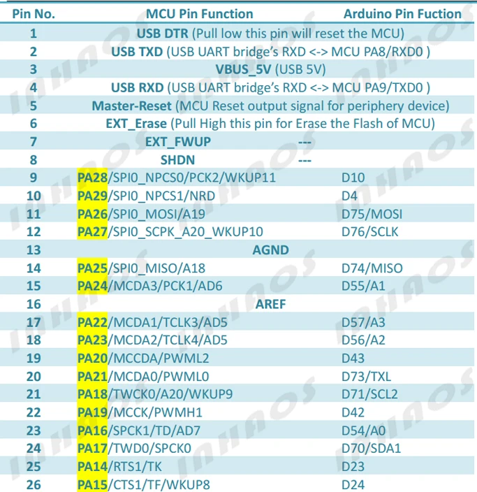
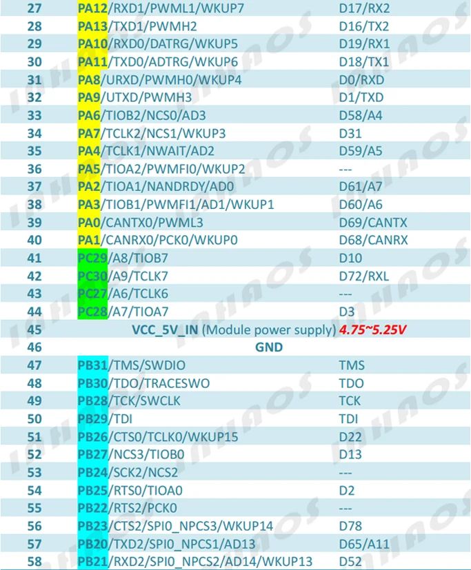
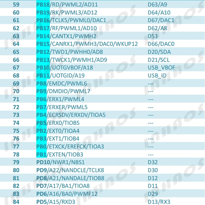

Notes:
1, D4 connected to both PA29 andPC26
2, D10 connected to both PA28 andPC29
3, The board can be powered by Pin45/46 VCC_5V_IN and GND , also can be powered by USB or Programming port.
4, If VCC_5V_IN and USB or Programming port are connected at the same time , the board will VCC_5V_IN is priority.
5, The VCC_5V_IN must limit tolerance within +/-5% , which means the voltage range is 4.75-5.25V
6, The GND(Pin-46) and AGND(Pin-13) are connected by onboard 0R resistor.
Typical application
Power Connection 1:
powered by Programming port, in this case , the module can be powered by VBUS_5V form the USB to UART cable (Recommend UC-2102). The connection as below :

Power Connection 2:
powered by VCC_IN_5V, in this case , The VCC_5V_IN must limit tolerance within +/-5% , which means the voltage range is 4.75-5.25V. The connection as below :

Power Connection 3:
Both Programming port and VCC_5V_IN are connected , In this case , the VCC_IN_5V is priority, The connection as below :

NOTE: THE POWER SUPPLY TO THE MODULE IS 5V , BUT THE MCU IS WOKING UNDER 3.3V , THE ONBOARD LDO WILL REGULATE THE 5V POWER TO 3.3V.