Description
1. All products in the store are not included: customs duties, customs clearance fees and tax. Without special requirements, we will declare them according to the price of the product.
2. We hope that you can understand the relevant taxation policies of your local customs. We do not accept your refusal for goods due to customs taxation issues; (in some countries, the platform has the option of pre-collecting tariffs).
3. In order not to affect your receipt of the goods, after purchasing the goods, please pay more attention to information such as emails, platform messages, etc. If there is any information about the unclear address or the logistics policy changes, we will notify you as soon as possible, and look forward to you reply.
DIY KIT Project
To complete this project, high level knowledge of electronics and rich experience in terms of soldering and testing are required.
Due to time zone and language communication restrictions, we can only provide limited technical support, and you need to solve problems by yourself.
We do not provide information other than the product introduction page.
MOFI-LDO5A Mosfet Linear Pwer Supply (SingleRail)5-24VDC 5A DIY KIT
use PMOS LDO architecture
Single-pass, series regulator design.
Low noise, high PSRR
A constant-current source feeds a zener diode as a stable voltage reference.
A low-pass filter (with a corner frequency of 3.2Hz) prevents zener noise from being introduced into the error amplifier.
The low-pass filter also provides a soft-start characteristic.
use a opamp as error amplifier to track output voltage stable as designed.
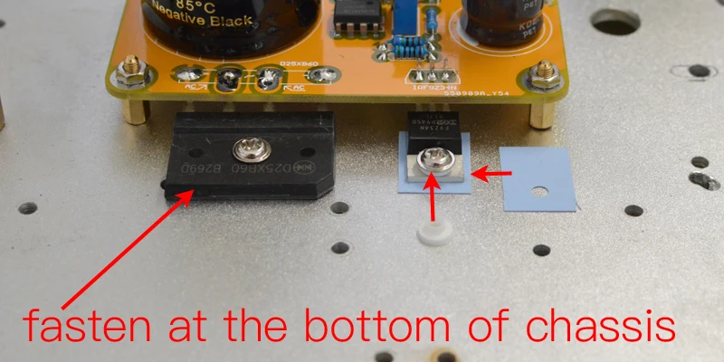
High-current MOSFET pass transistors
The high current rating provides a very high safety headroom against overcurrent damage。
More sustained currents are possible by using larger, offboard heatsinks.
The negative temperature coefficient of MOSFETs prevents damaging thermal-runaway conditions that may plague conventional BJT devices.
Use Schottky rectifier bridge
The output voltage is continuously adjustable from 5-24V, no additional replacement of components is required.
Do not short the output terminal to discharge capacitor, otherwise it will damage the power board.
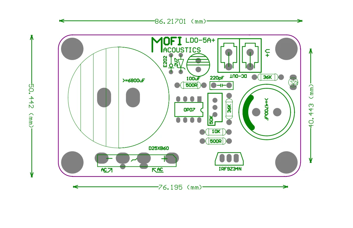
Product configuration
DIY kit: Contains the PCB and the components needed on the PCB, but does not include the power transformer .
Finished board: Based on the well-tested board on the standard version kit, we verified all key points' voltage, and used the signal generator and oscilloscope for analog waveform double verification. We will not use this board for listening test.
All finished pcbs are all carefully hand-soldered and fully tests, so the price is higher and less cost performance. Price-sensitive consumers but with have DIY ability are recommended to choose the kit.
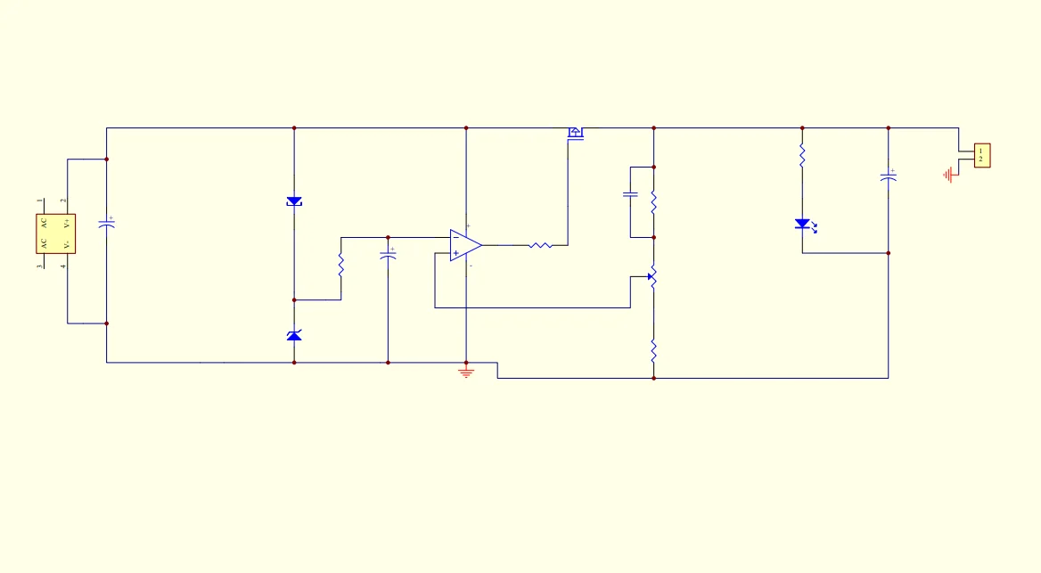
Schematic
PCB comes with component parameters for easy installation.
We only refer the schematic of the amplification part of the circuit. If you need full circuit parameter, please read the component value with the PCB by yourself; we do not provide additionally.
DIY KIT Instructions
Since the PCB holes are plated through, you only need to solder the parts from the bottom of the board. Do not drill or enlarge the holes because that would damage the through-plating.
Clean both sides of the blank PCB with paper towel and isopropyl alcohol or electronics flux remover, then solder the components to the board, starting with the lowest profile parts. This means the resistors and zener diode. Then solder the small capacitors, small transistors, followed by the larger capacitors.
Make sure the correct part goes into each position on the circuit board. Measure each resistor with your multimeter to ensure it's the proper value.
Pay attention to the polarity of electrolytic capacitors, diodes, , transistors as well as the orientation.
Clean up the solder flux residue from the board with isopropyl alcohol (or electronics flux remover) and a brush.
Inspect all solder connections carefully, using a magnifying glass, to make sure there are no solder bridges or cold solder joints. Use a multimeter in ohms scale to check for short circuits.
Typical Application
Input voltage VAC= (Output voltage +8)/1.414
Please reserve 30% redundant power for the transformer.
Transformer Power=VAC*I*(1+0.3).
12VDC-OUT-5A
Input voltage VAC=(12+8)/1.414=14.14VAC, Please choose 15VAC;
Transformer Power= (15*5)*(1+0.3)=97.5W; Please choose 100W
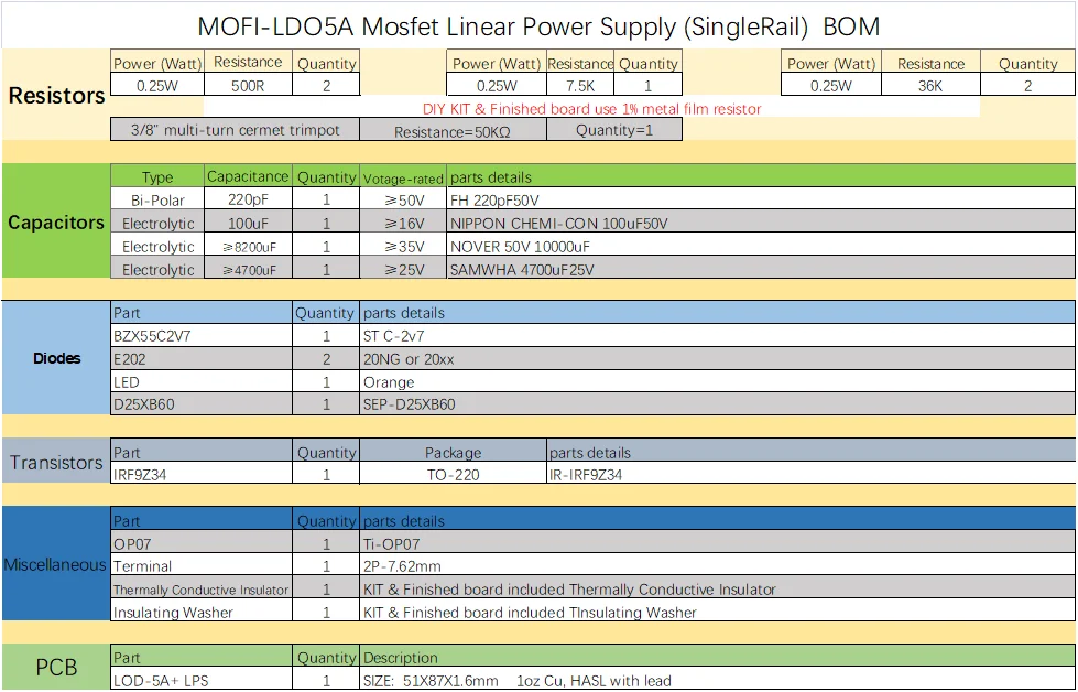
Parts list
Pics
DIY KIT


Pics
Finished board


