Item Details:
* brand new and high quality
*Made of high quality material, and practical to use
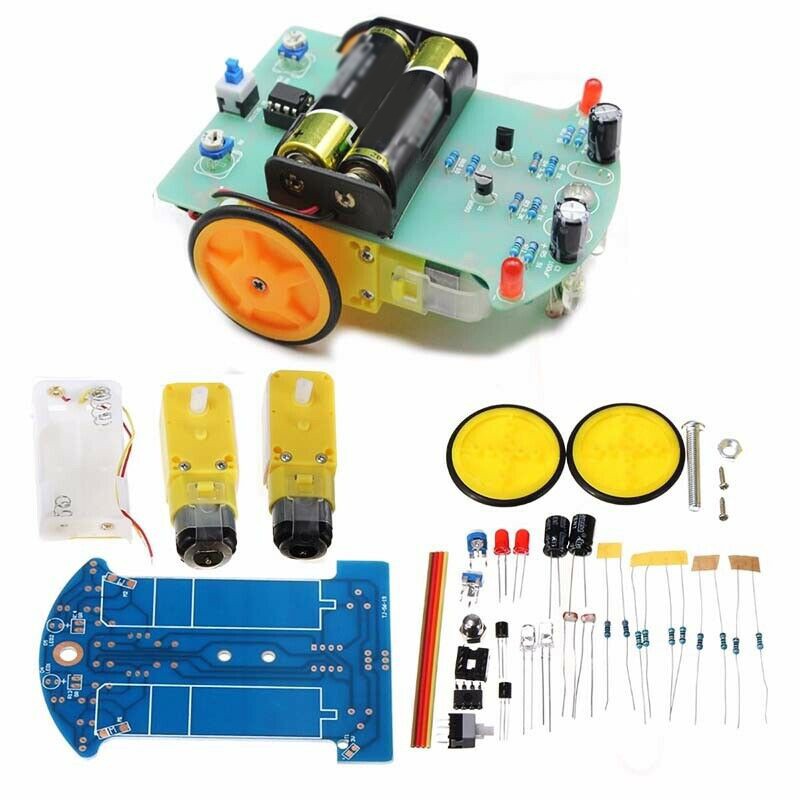
*Name: Tracking robot car
*The line based on photoresistor (LDR) is as follows
*Individual wheel control
*Chipset: LM393
*Material: Electrical components
*Color: As pictures show
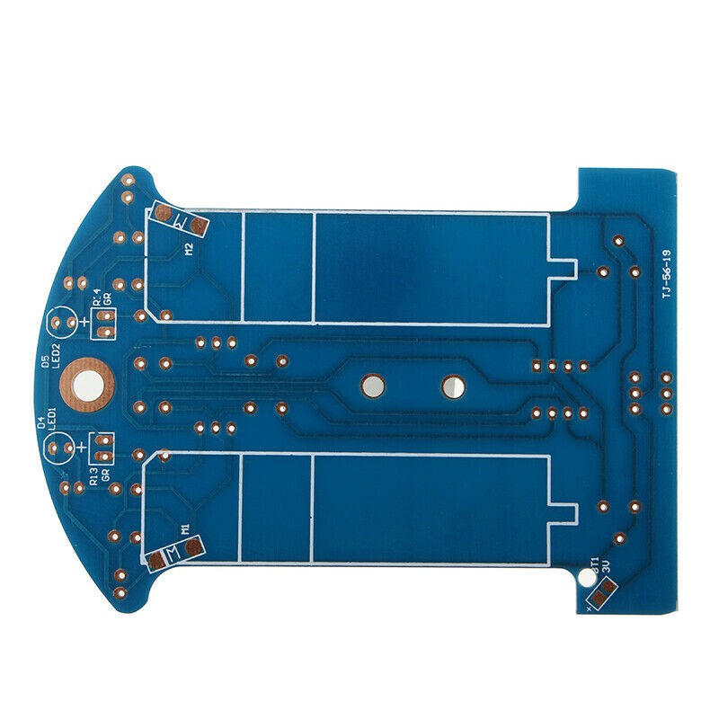
*Board size: 10.4 * 7.2 cm(Approx.)
Assembly Steps:
*Step 1: Welding circuit
The welding part is relatively simple, the welding order is based on the principle of the component level from low to high, the first welding eight-level resistance, it is important to use the multimeter to determine whether the resistance is correct.
*Step 2: Mechanical Assembly
The red line is connected to the 3V positive power supply, the yellow line is grounded, and the excess line can be used for the motor line.
*Step 3: Install the optoelectronic circuit
The photoresistor and LED (note the polarity) are mounted on the PCB in reverse, the ground distance is about 5 mm, and the distance between the photoresistor and the LED is 5 mm. Finally, you can perform the power test.
*Step 4: Vehicle commissioning
The correct direction is along the direction of the wheel. If you press the light resistor on the left side, you should rotate the wheel on the right side of the car. Press and hold the light resistor on the right side, the wheel on the left side of the car should rotate, if the car comes back, It is also possible to replace the wiring of the two motors, if side is normal and the other side is rearward, because you can exchange the wiring on the back side.
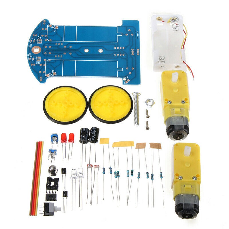
Package Contents:
1*Bottom Plate
2*35 mm Wheels
2*Rubber Wheels
1*AA Battery Holder
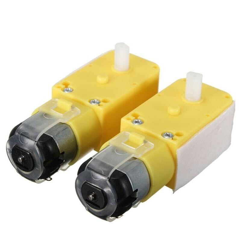
2*Intelligent DC Motors
1*Screw Set
1*LM393 Chipset
1*8pin DIP Socket
10*Resistors
2*Electrolytic Capacitors
2*Photoresistors
2*Transitors
2*White LEDs
2*Red LEDs
1*Power Switch
4*70mm Wires
Note:
1.The real color of the item may be slightly different from the pictures shown on website caused by many factors such as brightness of your monitor and light brightness.
2.Please allow slight manual measurement deviation for the data.