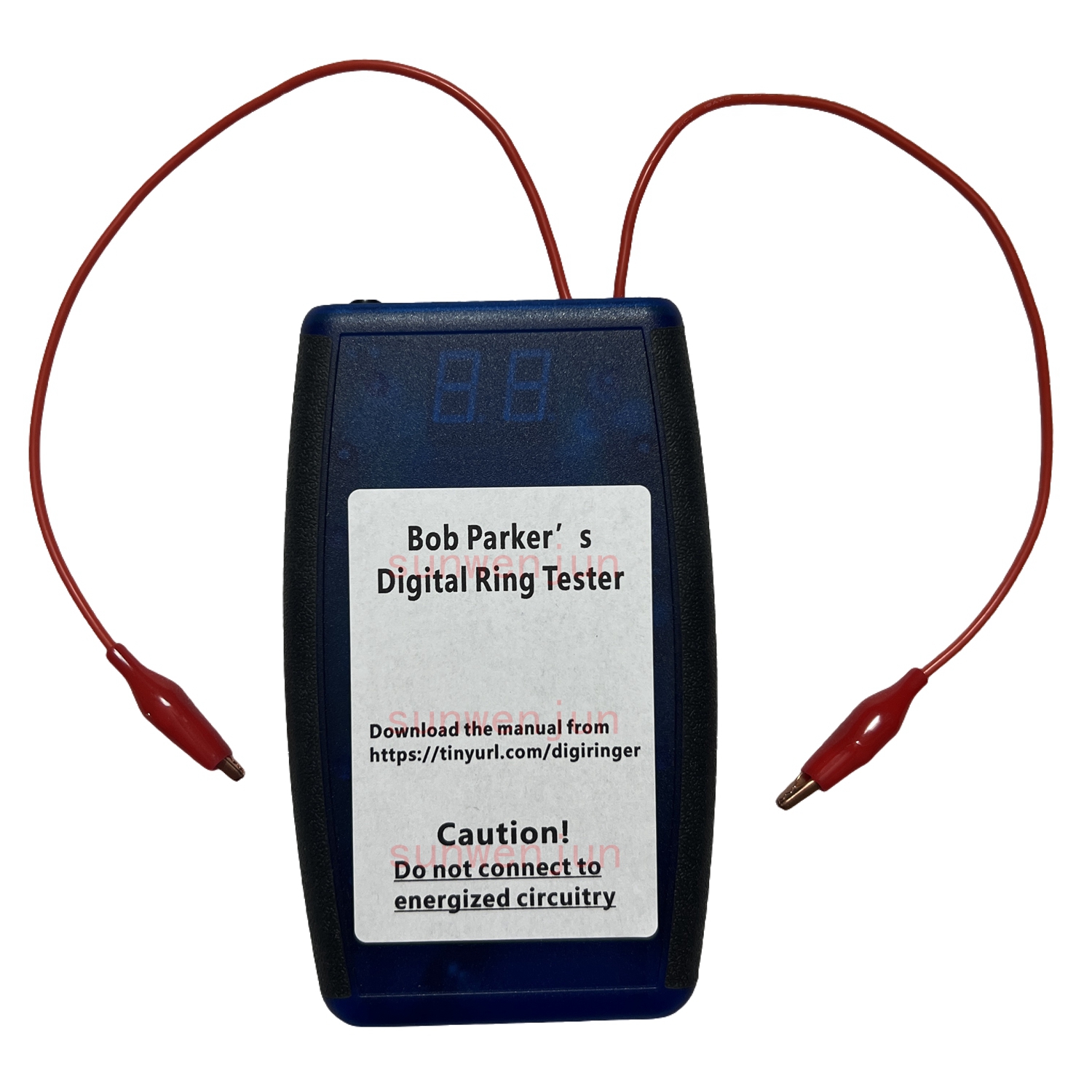
Bob's Basic Wide Range Ring Tester for Inductors & Transformers, Comparable to Blue RingTester, CMOS ICs
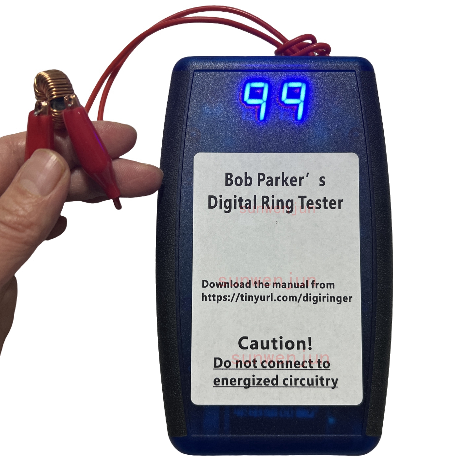
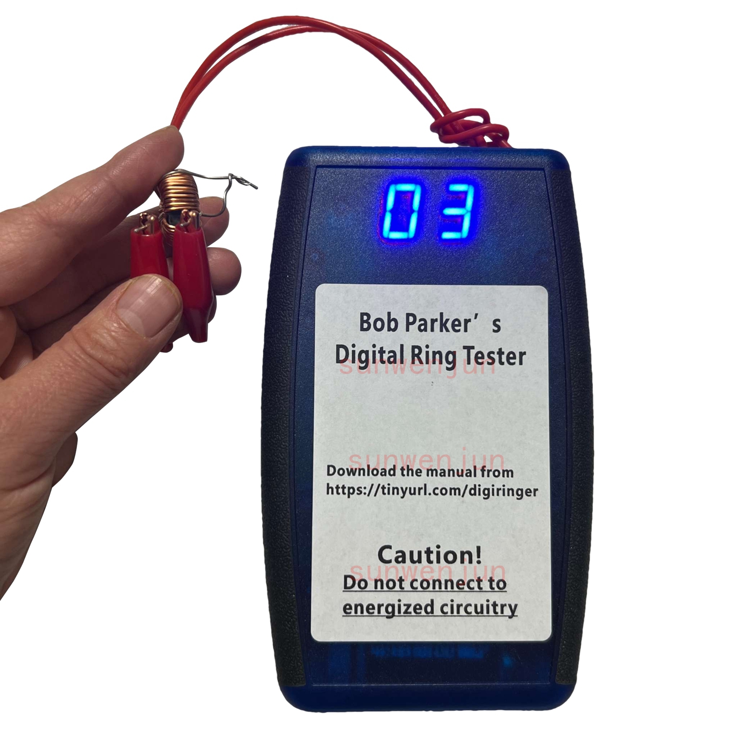
Please note: The picture is just to show the measurement result. The package does not include any batteries.
Overview of Bob's Basic Wide Range Ring Tester
For more information, please refer to the Youtube video.
https://www.youtube.com/watch?v=BgkR4e1XfhU&t=40s
https://www.youtube.com/watch?v=ZIQkxwHbHKs
Design and Comparison:
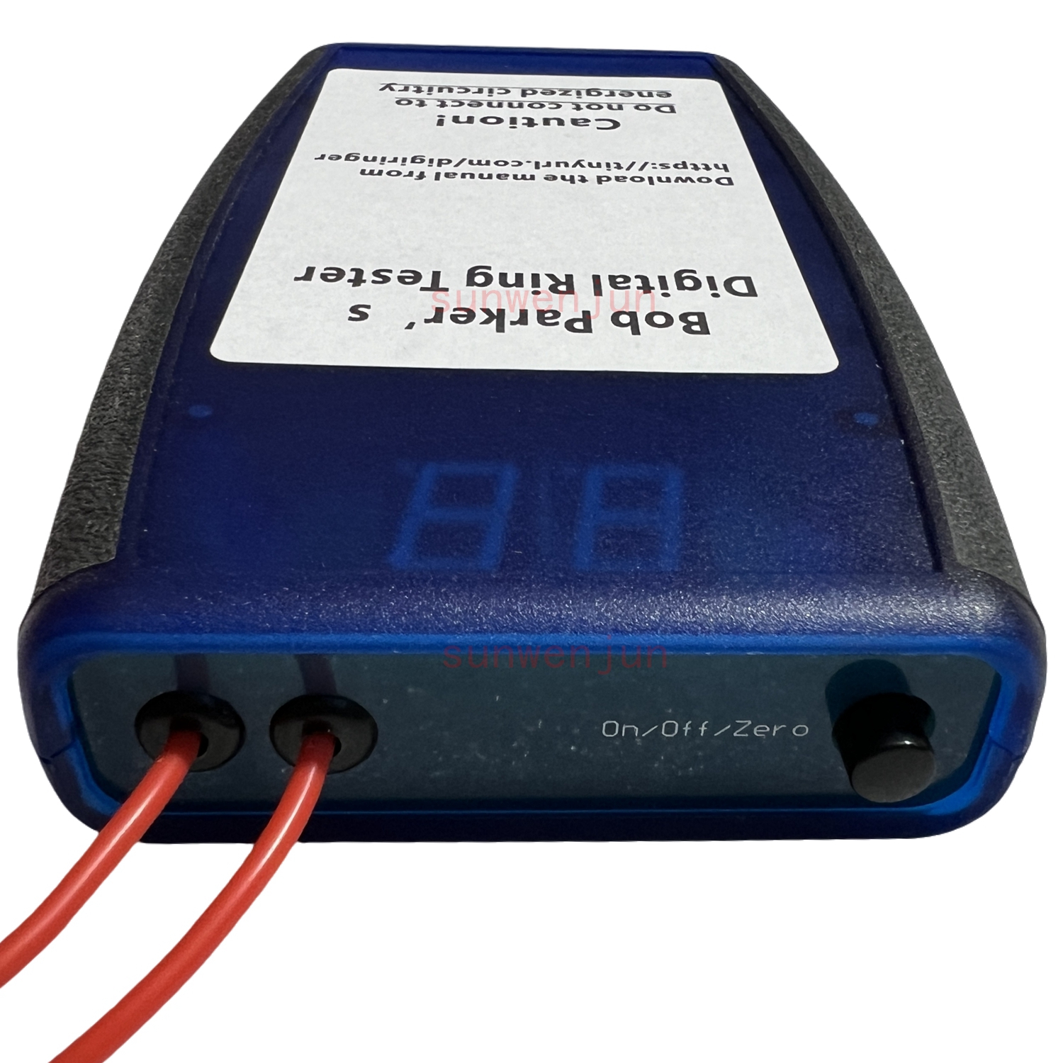
Bob designed a basic version of the "Blue2" microcontroller-based wide range ring tester called the basic wide range ring tester. Unlike the "Blue2," this version utilizes 4000 series CMOS ICs and through-hole components, making it accessible for individuals with electronic skills to build. It is larger than "Blue2" and operates on a 9V alkaline battery with manual power control through a push-on/push-off button. It lacks automatic turn-off and low battery warning features.
Operational Principle:
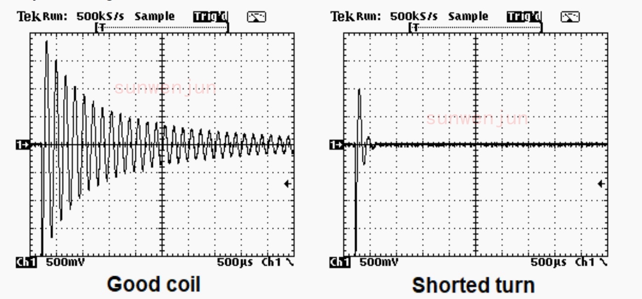
The tester operates by discharging a low-loss polypropylene capacitor, which is charged to 2V, into an inductor approximately five times per second. A functioning inductor or transformer winding will form a resonant circuit that produces a ringing waveform. If short-circuited turns are present, they dampen the resonant circuit, reducing the ringing.
Circuit Description:
The device uses the same front-end circuit as the "Blue2," where the waveform is fed into a high-impedance JFET buffer. The waveform is then processed by half of an LM393 dual comparator with hysteresis to generate square waves until the ringing voltage decays to about 30mV peak-to-peak. The resulting square waves are counted by a CD4518B dual decade counter. The counts are displayed using a pair of CD4511B latch/decoder/7-segment driver ICs. An additional feature prevents the counter from resetting incorrectly if it reaches 99.
Theoretical Use:
The tester is useful for diagnosing faults in inductive components such as transformers and chokes found in electronic equipment like switch mode power supplies, LCD backlight inverters, and older CRT transformers. These components are often expensive and hard to replace, making accurate diagnosis essential.
Testing Methodology:
The tester is capable of testing both high-frequency types with ferrite cores and low-frequency iron-cored transformers. It outputs a low voltage that usually allows inductive components to be tested in-circuit unless other circuit faults interfere. For definitive results, components should be tested individually.
Interpreting Results:
High-quality ferrite-cored transformers typically show readings between 50 and 99 rings. A reading below 10 usually indicates shorted turns. However, anomalies like a fully shorted secondary winding could misleadingly show higher readings, such as 37 rings. The effect of partial shorts in primary windings can be tested by inducing shorts in secondary windings, providing a comparative analysis between suspected and known good transformers. Low-frequency transformers typically show lower readings due to the nature of their operation and materials.
Recommendations for Use:
Bob encourages extensive use of the tester on various transformers and inductors to develop a practical understanding of typical readings, as these can vary widely across different types and models of inductive components.