
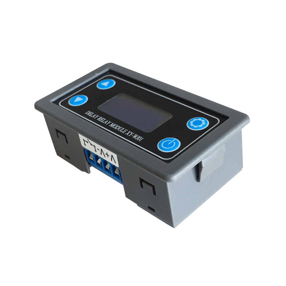
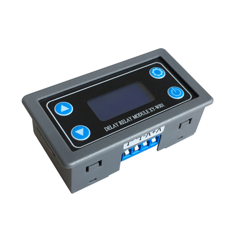
DC 6-30V Time Delay Relay Module Programmable Timer Relay Control Switch Circuit Timing Trigger Cycle with LCD Digital Display
Features:
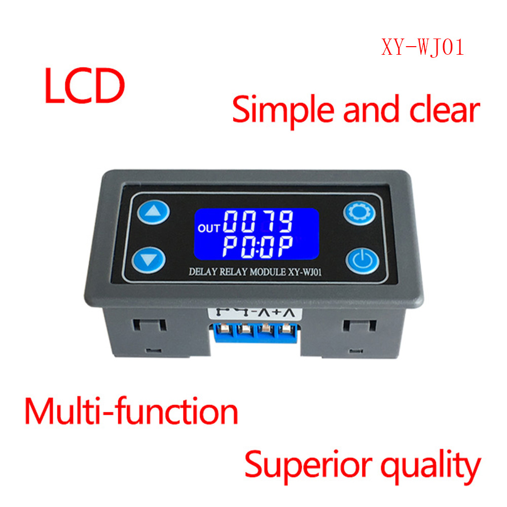
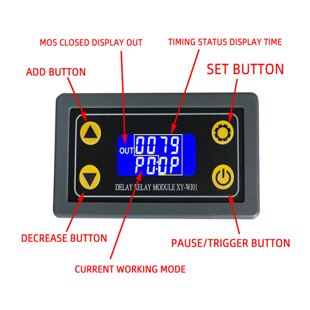
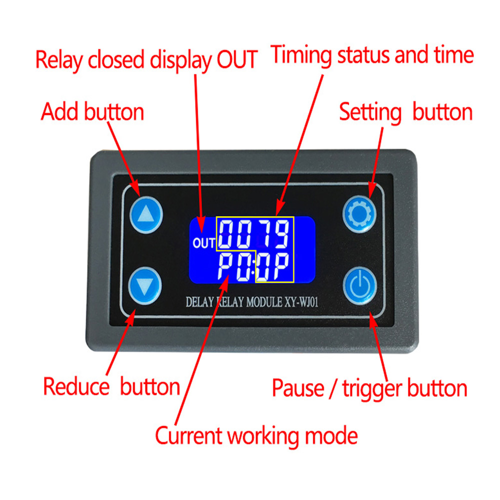
1.Display with LCD two columns, Can display parameters directly.
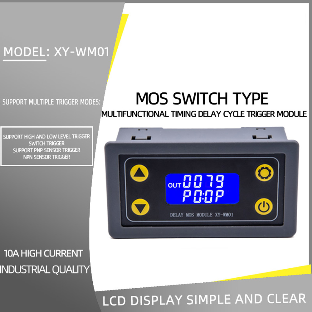
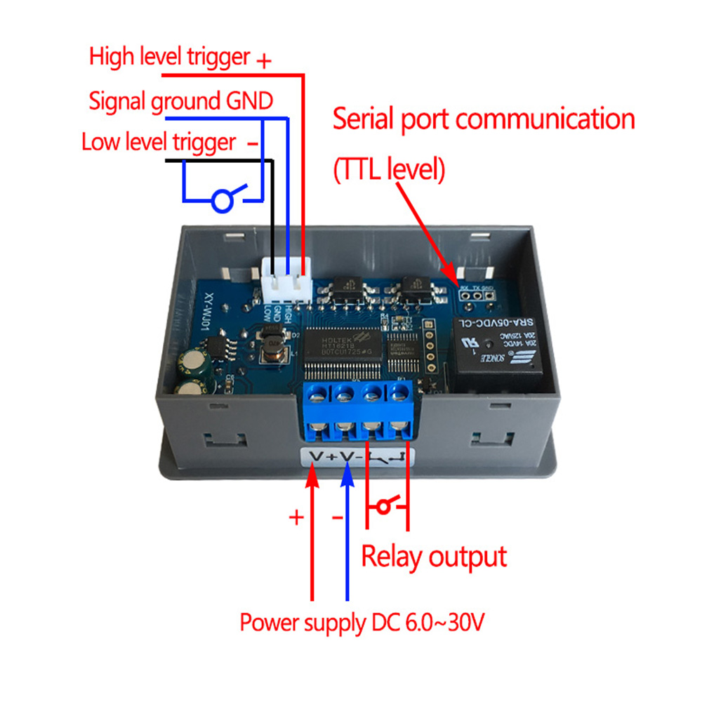
2.Trigger mode: high and low level,switch quantity.meet most of the needs.
3.Parameters can be modified via UART.
4.Stop button to provide emergency stop function.
5.5 minutes without any operation into a low-power state. Any action wake up.
6.OP/CL/LOP params can be modified individually.
7.All parameters are automatically saved by power off.
Specifications:
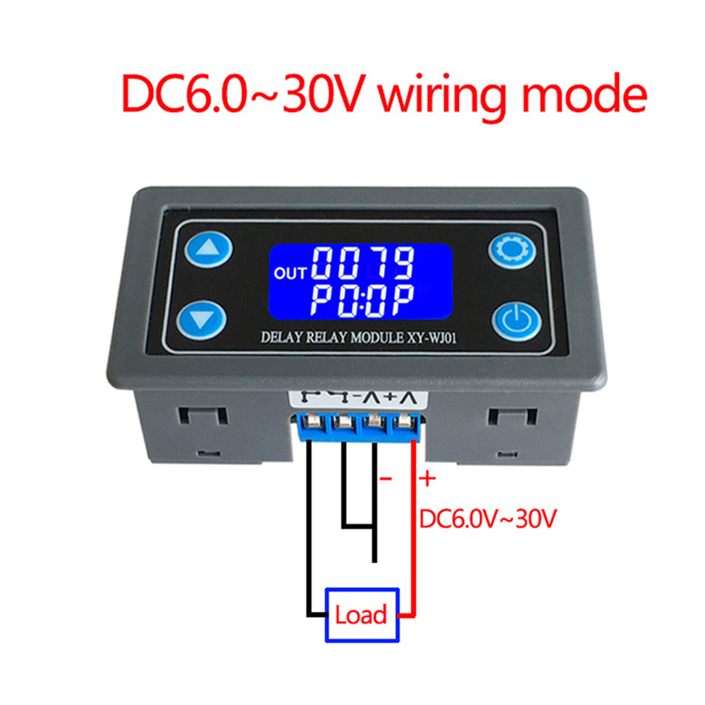
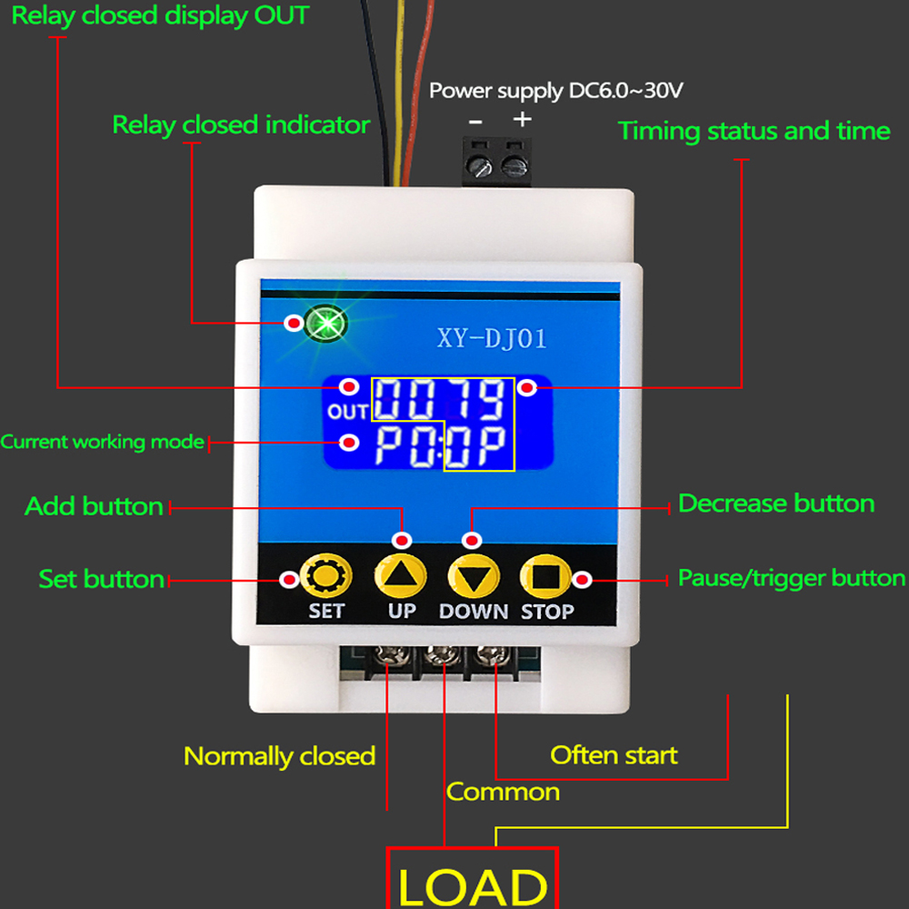
Power Supply: 6V~30V
Trigger signal source: High level(3.0V~24.0V),Low level(0.0V ~0.2V),Switch signal
Maxmum Output load:
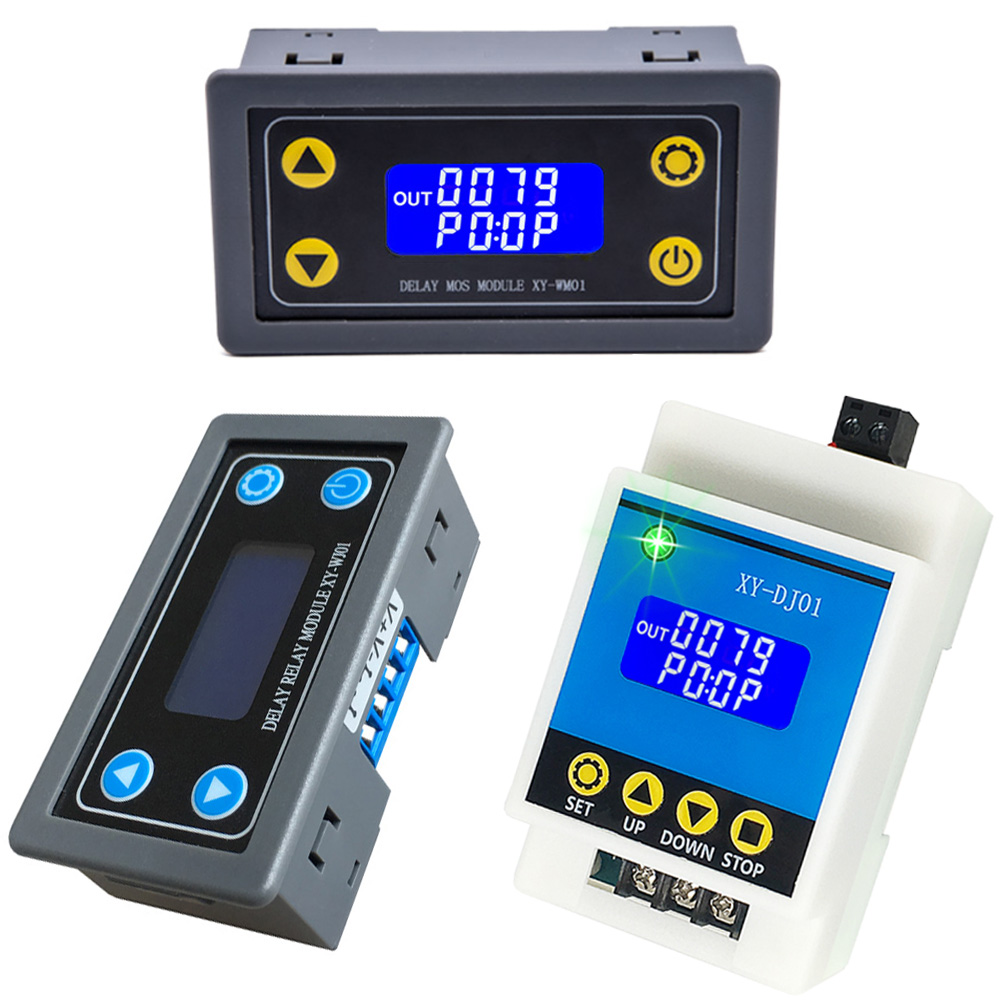
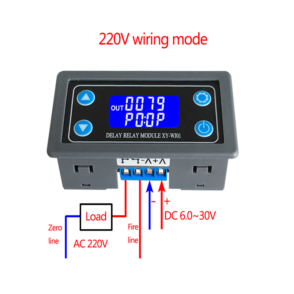
XY-WJ01: DC 30V 10A and AC 220V 5A
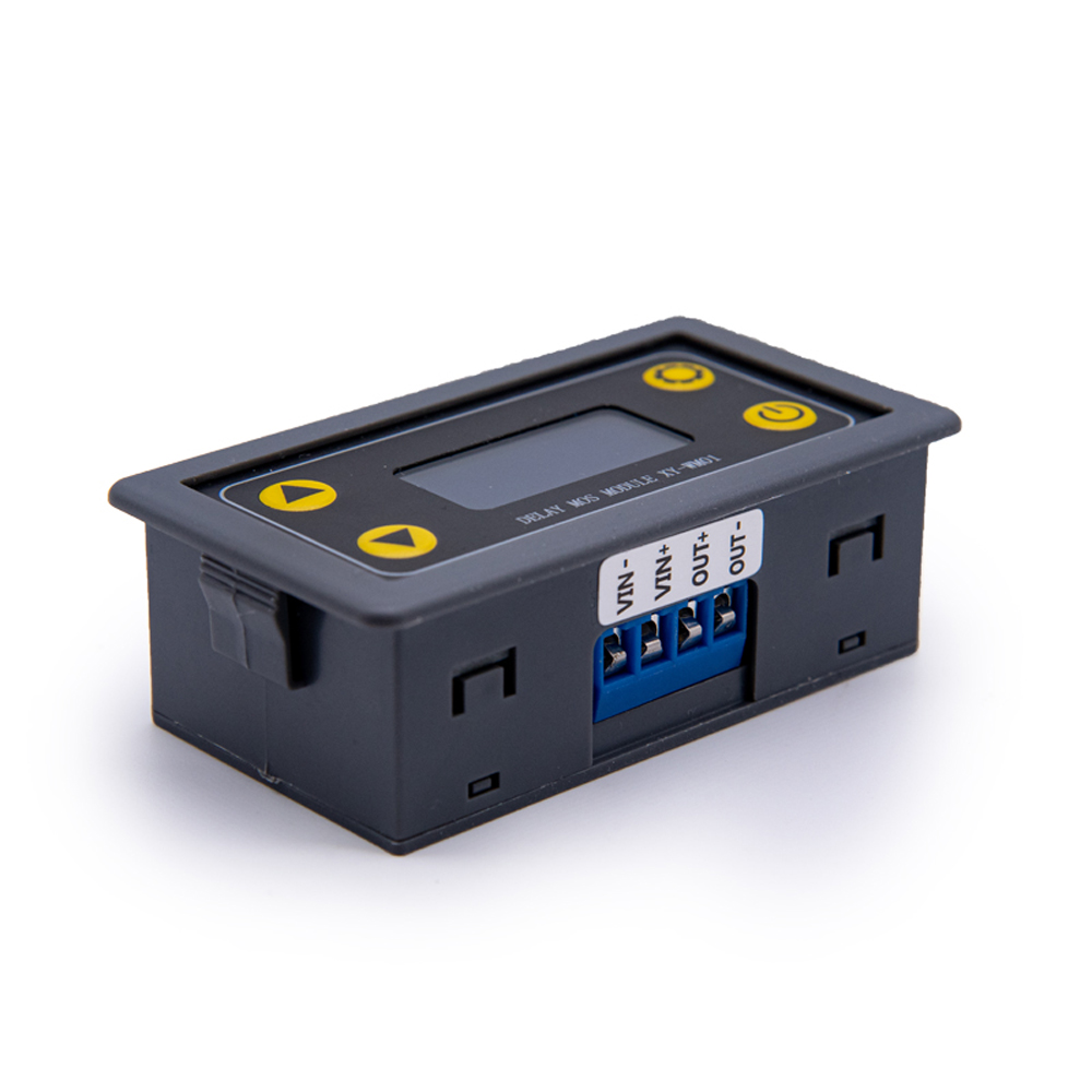
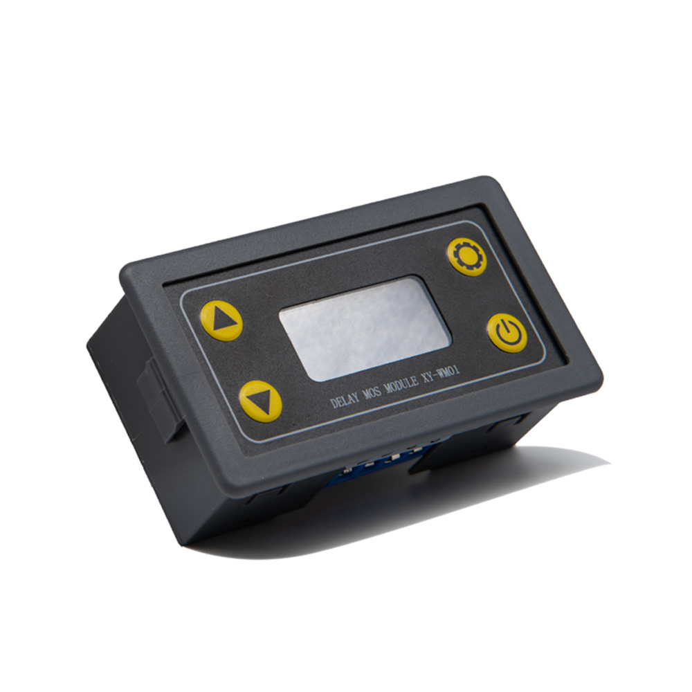
XY-WM01: DC 30V 10A
XY-DJ01: DC 30V 30A and AC 220V30A
Static Current: 15mA
Operating current:
50mA(XY-WJ01,XY-WM01)
50mA-130mA(XY-DJ01)
Service life: more than 100,000 times
Working temperature: -40-85°C
Size:
XY-WJ01: 7.1*3.9*2.5cm
XY-WM01: 7.9*3.8*4.3cm
XY-DJ01: 9.8*5.5*4.4cm
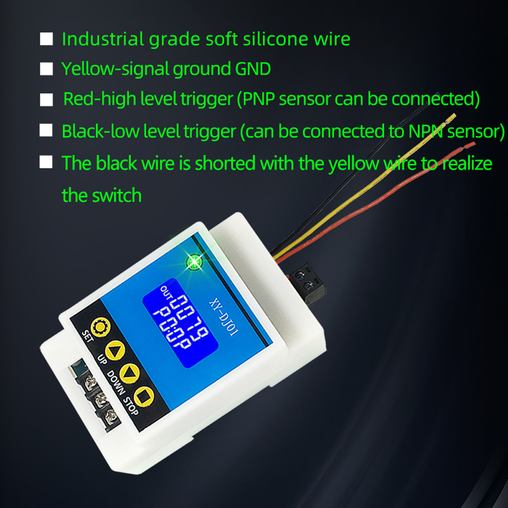
Optocoupler isolation,Strong anti-interference ability, Industrial grade circuit board, after power set parameters memory forever
Working Mode Introduction(P1~P7):
P0: After the signal is triggered, the MOS conduction in OP time then disconnects; In the OP time, the signal is invalid.
P1: After the signal is triggered, the MOS conduction in OP time then disconnects; In the OP time, the signal triggers a new timer.
P2: After the signal is triggered, the MOS conduction in OP time then disconnects; In the OP time, signal trigger reset timer, MOS disconnected and stop timing.
P3: After the signal is triggered, the MOS disconnects the CL time, and then the MOS conduction.
P4: After the signal is triggered, the MOS conduction the OP time, and then the MOS disconnects the CL time, and then loops the above action, gives the signal again in the loop, MOS disconnect, stops the timer; and the number of cycles (LOP) can be set; End of cycle, keep MOS disconnected;
P5: After the signal is triggered, the MOS disconnects the CL time , and then the MOS conduction the OP time, and then loops the above action, gives the signal again in the loop, MOS conduction, stops the timer; and the number of cycles (LOP) can be set; End of cycle, keep MOS conduction;
P6: No trigger signal after power-on, After the MOS conduction OP time, the MOS disconnects the CL time, and then loops the above action, signal is invalid in the loop, the number of cycles (LOP) can be set; End of cycle, keep MOS disconnected;
P6: No trigger signal after power-on, After the MOS disconnects the CL time, the MOS conduction OP time, and then loops the above action, signal is invalid in the loop, the number of cycles (LOP) can be set; End of cycle, keep MOS conduction;
P8: Signal hold function: The signal is maintained, the timing is cleared, and the MOS conduction; when the signal disappears, the MOS disconnects after the timing OP; during the timing, there is another signal and the timing is cleared;
P9: Signal hold function: The signal is maintained, the timing is cleared, and the MOS disconnected; when the signal disappears, the MOS conduction after the timing CL; during the timing, there is another signal and the timing is cleared;
(P0~P7) mode, short press the pause button, Start timing if the system is not timed; If the system is already timed, the system pauses the timer, the MOS disconnected, flashing "out" to indicate a reminder;
P8/P9 mode, The pause button as a trigger signal in the Run interface, Short / Long press fail.
Timing Range:
0.01sec~9999 min
How to choose the timing range:
In the OP/CL parameter modification interface, press the pause button shortly to select the timing range.
XXXX Timing range:1sec~9999sec
XXX.X Timing range:0.1sec~999.9sec
XX.XX Timing range:0.01sec~99.99sec
X.X.X.X Timing range:1min~999.9min
For example, if you want to set the OP to 3.2 seconds, move the decimal point to ten digits. LCD display 003.2
Parameter Description: OP on-time, CL off time, LOP cycle times (1 - 9999 times, "----" represents an infinite number of cycles)
Parameter Settings:
a)Press and hold the SET key to enter the setting interface;
b)First set the working mode, work mode flashes reminder, set the working mode by pressing the UP / DOWN keys;
c)Short press the SET button to select the working mode and enter the system parameter settings.
d)In the system parameter setting interface, press SET key to switch the system parameters to be modified, and press / long press UP/DOWN key to modify. (Note: Short press SET in P0~P3/ P8/P9 mode is invalid);
e)In the OP/CL parameter modification interface, short press STOP to switch the timer unit (1s/0.1s/0.01s/1min);
f)After all parameters are set, press and hold the SET button for more than 2 seconds to release the hand, save the parameter settings and exit the setting interface.
Note:
1. Due to the light and screen difference, the item's color may be slightly different from the pictures.
2. Please allow 1-3cm differences due to manual measurement.
Package Included:
1x Relay Module