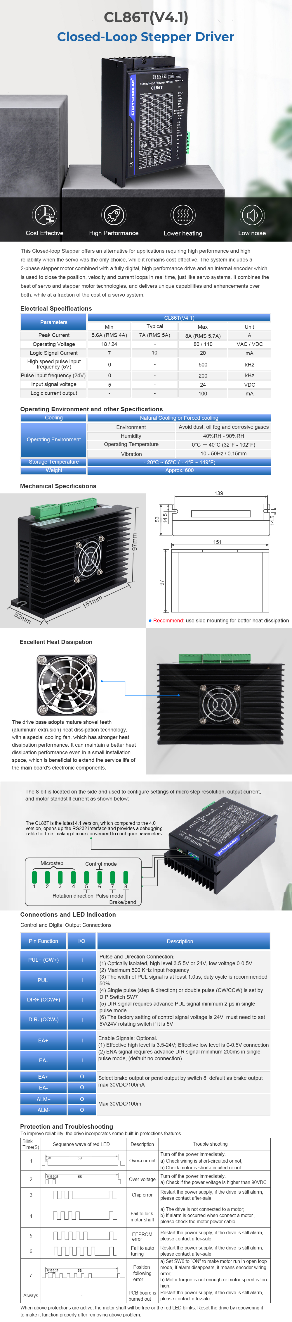
This Closed-loop Stepper offers an alternative for applications requiring high performance and high reliability when the servo was the only choice, while it remains cost-effective. The system includes a 2-phase stepper motor combined with a fully digital, high performance drive and an internal encoder which is used to close the position, velocity and current loops in real time, just like servo systems. It combines the best of servo and stepper motor technologies, and delivers unique capabilities and enhancements over both, while at a fraction of the cost of a servo system.
Package include:
- 1 x Closed Loop Stepper Driver 0-8.2A 24-80VDC for Nema 34 Stepper Motor CL86T V4.1
- 1 x Nema 34 Closed Loop Stepper Motor 12.0Nm(1699.68oz.in) Encoder 1000CPR
- 1 x 1.7m Long Encoder Extension Cable for Closed Loop Stepper Driver
- 1 x RV-4 AWG18 1.7m Long Motor Extension Cable with GX16 Aviation Plug
- 1 x RS232 Debugging Cable
Motor Specification
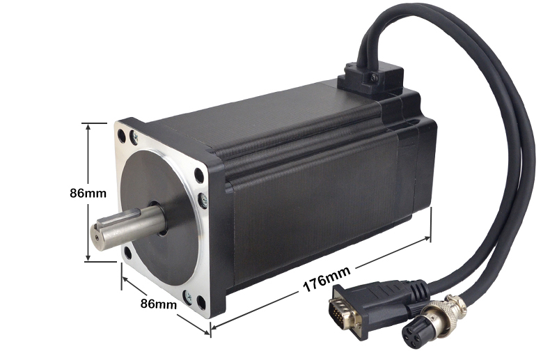
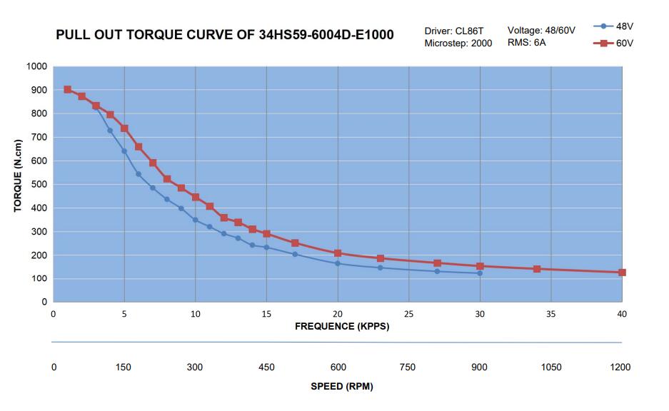
Part Number: 34HS59-6004D-E1000
Number of phase: 2
Holding Torque: 12.0 Nm(1699.68oz.in)
Rated Current/phase: 6.0 A
Phase Resistance: 0.7 ohms± 10%
Inductance: 7.9 mH ± 20%(1KHz)
Frame Size: 86 x 86 mm
Body Length (without Encoder): 150.5 mm
Full Length ( with Encoder): 169mm
Shaft Diameter: 14 mm
Shaft Length: 37 mm
Keyway Shaft Length: 25 mm
Lead Length: 300 mm
Encoder Specification
Output Circuit Type: Differential type
Encoder Type: Optical Incremental
Encoder Resolution: 1000PPR(4000CPR)
Output Signal Channels: 2 channels
Supply Voltage Min: 4V
Supply Voltage Max: 5V
Output Current: 100mA
Output High Voltage: 5V
Output Low Voltage: 4.5V
Output Frequency Max: 60kHZ
Encoder Type: Optical Incremental
Encoder Resolution: 1000PPR(4000CPR)
Output Signal Channels: 2 channels
Supply Voltage Min: 4V
Supply Voltage Max: 5V
Output Current: 100mA
Output High Voltage: 5V
Output Low Voltage: 4.5V
Output Frequency Max: 60kHZ
Motot and Encoder Connection
|
PIN
|
1
|
2
|
3
|
4
|
|
Motor
|
A+
|
A-
|
B+
|
B-
|
|
PIN
|
2
|
3
|
1
|
13
|
11
|
12
|
|
Encoder
|
VCC
|
EGND
|
EA+
|
EA-
|
EB+
|
EB-
|
Motor Extension Cable Connection
|
PIN
|
1
|
2
|
3
|
4
|
|
Color
|
Black
|
Green
|
Red
|
Blue
|
Encoder Extension Cable Connection
|
PIN
|
2
|
3
|
1
|
13
|
11
|
12
|
|
Color
|
Red
|
White
|
Black
|
Blue
|
Yellow
|
Green
|
PLEASE NOTE: The thick black wire can be used for shielding, but it is not required, so you can leave it unconnected.
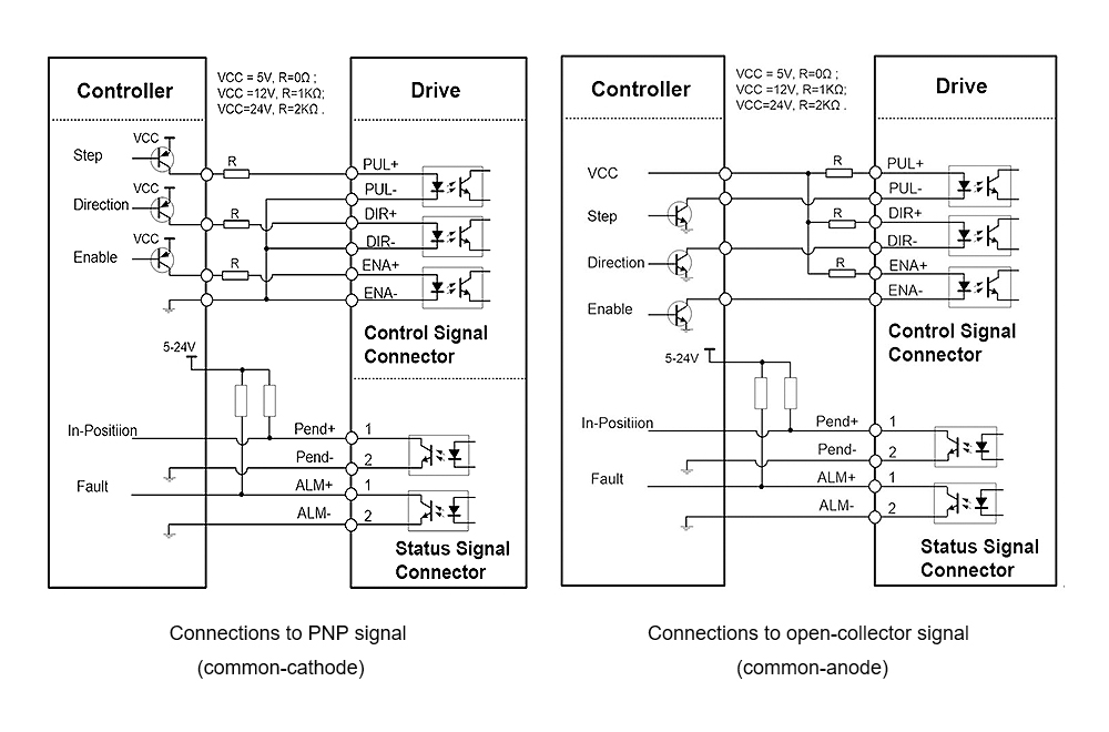
Typical Connection
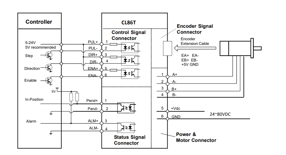
Control Signal Wiring
Questions & Answers
1. What size is the motor shaft
14mm dia with a 5mm key
2.What the maximum RPM is?
maximum rpm is 2000rpm
3.The motor do not turn when the pulse input
1.Whether the pulse input of the driver is connected stably
2.Whether the input way in the system configuration of the driver is pulse input
3.Whether the motor can be released
4.Power LED does not light after power
1.Check the connection of the power line.
2.the voltage maybe too low
5.Red light warning
1.check the connection of the motor with power
2.input voltage of the driver maybe too low or too high
6.Red light alarm after running a small angle
1.Whether the phase wire of the motor is correctly connected. If it is not correct, please refer to the motor phase and the corresponding phase sequence of the driver.
2.In the driver configuration parameters, whether the number of motor encoder lines is consistent with the connected motor parameters. If they are different, you need to reset them.
3.Whether the pulse input speed is greater than the rated speed of the motor
Why StepperOnline ?
- Over 10,000 Products In Stock:
Our veteran engineers selected hundreds of typical models from our sales records, and we stocked in our warehouse. More than 10,000 products are ready to ship and we promise delivery your goods in 24 Hours!
- Low Prices Direct From Factory Suppliers:
As a China-based distributor, StepperOnline has developed long lasting ties with more than 50 factories. We purchasing products with huge quantity to lower the cost as possible. Even our prices are lower than the price you get from manufacturer directly.
- Fast Delivery Around The Globe:
During 2015, we have built four warehouses which located in US, UK, Germany and Australia. Partnering with local logistic service providers, we can ship faster and receive return goods more easily.
- High Quality With Global Standards:
Cooperate with Top 3 famous manufacturers to make sure the products are produced with high quality, and in-house QC dep., ensuring each and every item purchased meets global quality standards.
- Customer Service & Technical Support:
You will get in touch with StepperOnline through Telephone, Email and also online Live Chat, our engineer are ready to serve you!
- Flexible Customization:
Small quantity, and customized products are available, we will delivery your samples within incredible short time.
Feedback & Contact
- We strive to maintain the highest standards of excellence for shopping experience and 100% customer satisfaction!
- Positive feedback is very important to us. We sincerely request that you contact us immediately before you give us neutral or negative feedback, so that we can satisfactorily solve your concerns.
- For anything questions about product, price, shipping or order status, please contact us by using message or online chat tool.
Warranty & Refund
- All items sold are brand new and 1 YEAR WARRANTY after sales.
- If you receive a wrong or defective item please email us within 7 days from the date you receive the product.
- Later than 15 days the item cannot be accepted for returning.
- If the goods are defective, we will send replacement parts or refund to you after receiving the proof of the defective photos of the items that you received. Shipping and handling are not refundable.
- Due to custom restrictions, please contact Stepperonline Customer service before you return the goods.