Waterproof Ultrasonic Ranging Module JSN-SR04T Distance Measuring Transducer Sensor JSN-SR04T 2.0 for Arduino DIY Electronic
Product Features:
JSN-SR0T4-2.0 ultrasonic distance measuring module can provide 20cm-600cm non-contact distance sensing function, ranging accuracy up to 2mm; module includes transceiver ultrasonic sensor and control circuit. It is a piezoelectric sensor made using electrostrictive phenomena. An alternating voltage is applied to a piezoelectric material slice (for example, a quartz crystal, a piezoelectric ceramic, a lead titanate titanate, etc.) so that it generates electrostrictive vibration and generates ultrasonic waves. When the frequency of the applied alternating voltage is equal to the natural frequency of the wafer and resonance occurs, the generated ultrasonic wave is the strongest. Piezoelectric ultrasonic receivers generally use the inverse effect of ultrasonic generators to work. Their structure is basically the same as that of ultrasonic generators. Sometimes they use the same transducer as both the generator and the receiver. When the ultrasonic wave acts on the piezoelectric wafer to make the wafer expand and contract, an alternating charge is generated on the two interfaces of the wafer and then converted into a voltage and then amplified and sent to a measuring circuit for recording or displaying.
This product uses industrial-grade integrated ultrasonic probe design, a certain degree of waterproof (but can not be immersed in water), stable performance, compatible with all MCU work on the market.
small size, easy to use;
wide power supply range, low power consumption;
high measurement accuracy, high resolution
the detection of blind area is small, farther away;
output diversification, pulse width output, serial output
Product parameters:
Operating voltage: DC 3.0~5.5V
Operating current: less than 8mA
Probe frequency: 40kHz
Long range up to: 600cm
Near Range: 20cm
Distance accuracy: +-1cm
Measuring angle: 75 degrees
Input trigger signal:
1, TTL pulse above 10uS
2, serial transmission instructions 0X55
Output reverb signal: output pulse width level signal, or TTL
Wiring:
3-5.5V (power positive)
Trig (control) RX
Echo (output) TX
GND (power negative)
Product Size: L*W*H=42*29*12mm
Working temperature: -20~70 degrees Celsius
Product color: PCB board is blue

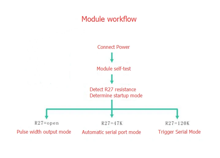
The default working mode is Mode 1.
Mode 1: R27 = open that is not welding. The pattern is described below
Basic working principle:
Using IO port TRIG trigger range, to a minimum of 10us high letter.
Module automatically send 8 40khz square wave, automatically detect whether the signal back;
There is a signal to return, through the IO port ECHO output a high level, the high level of continuous time is the ultrasound
From the time of launch to return. Test distance = (high time * sound velocity (340M / s)) / 2;
When the module is triggered, if no echo is received (the reason is more than the measured range or the probe is not positive On the measured object),
ECHO port will automatically become low after 60MS, marking the end of the measurement, regardless Power or not.
LED indicator, LED non-power indicator, it will receive the trigger signal after the module, this When the module is in working condition.
Only need to provide a pulse above 10uS trigger signal, the module will be issued within 8 40kHz cycle levels and detect echo. The echo signal is output once an echo signal is detected. Reverberations
The pulse width of the pulse is proportional to the measured distance. Thereby by transmitting a signal to the received echo signal time interval
Can calculate the distance. Formula: uS / 58 = cm or uS / 148 = inches; or: distance = high time *Sound speed (340M / S) / 2;
The recommended measurement period is 60ms or more to prevent the impact of the transmitted signal on the echo signal.
Mode 2: R27 = 47K is the welding 47K resistance. The pattern is described below
Serial output format for the TTL level, that: 100MS module for the cycle of automatic transmission
The value of the distance, in mm. Serial baud rate: 9600, n, 8,1.
Module power recognition, directly into the work mode, the module to conduct a distance every 100ms range,
And outputs one frame from the pin TX with four 8-bit data. The frame format is: 0XFF + H_DATA + L_DATA + SUM
1.0XFF: for a frame to start the data, used to judge;
2.H_DATA: the upper 8 bits of the distance data;
3.L_DATA: the lower 8 bits of the distance data;
4.SUM: data and, for the effect of its 0XFF + H_DATA + L_DATA = SUM (only low 8)
Note: H_DATA and L_DATA synthesize 16-bit data, that is, the distance in millimeters.
Description: The module outputs the nearest distance value in the dead zone. If the module does not measure data or is out of range Measured output 0.
LED indicator, LED non-power indicator, the module connected to work after the light, then the module is in Working state.
Mode 3: R27 = 120K is the welding 120K resistance. In the serial port mode
Module power recognition, the module into the standby state, the serial output format for the TTL level, the serial port baud rate:
9600, n, 8, 1. When the RX port receives the 0X55 instruction, the module starts a ranging and outputs from the pin TXOut of a frame with 4 8-bit data.
The frame format is: 0XFF + H_DATA + L_DATA + SUM
1.0XFF: for a frame to start the data, used to judge;
2.H_DATA: the upper 8 bits of the distance data;
3.L_DATA: the lower 8 bits of the distance data;
4.SUM: data and, for the effect of its 0XFF + H_DATA + L_DATA = SUM (only low 8)
Note: H_DATA and L_DATA synthesize 16-bit data, that is, the distance in millimeters
Description: The module outputs the nearest distance value in the dead zone. If the module does not measure data or is out of range Measured output 0.
LED indicator, LED non-power indicator, it will receive the 0X55 trigger signal in the module, this When the module is in working condition.