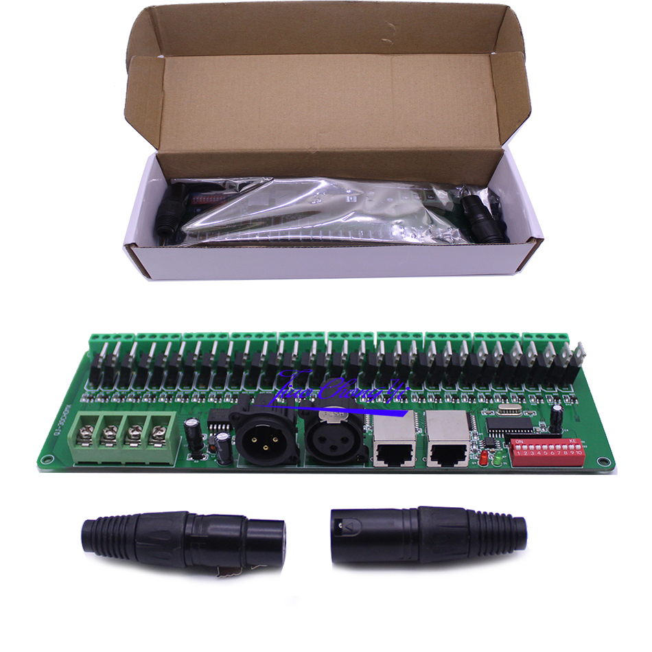
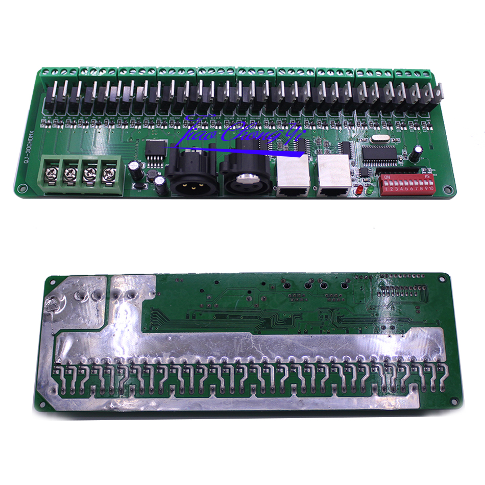
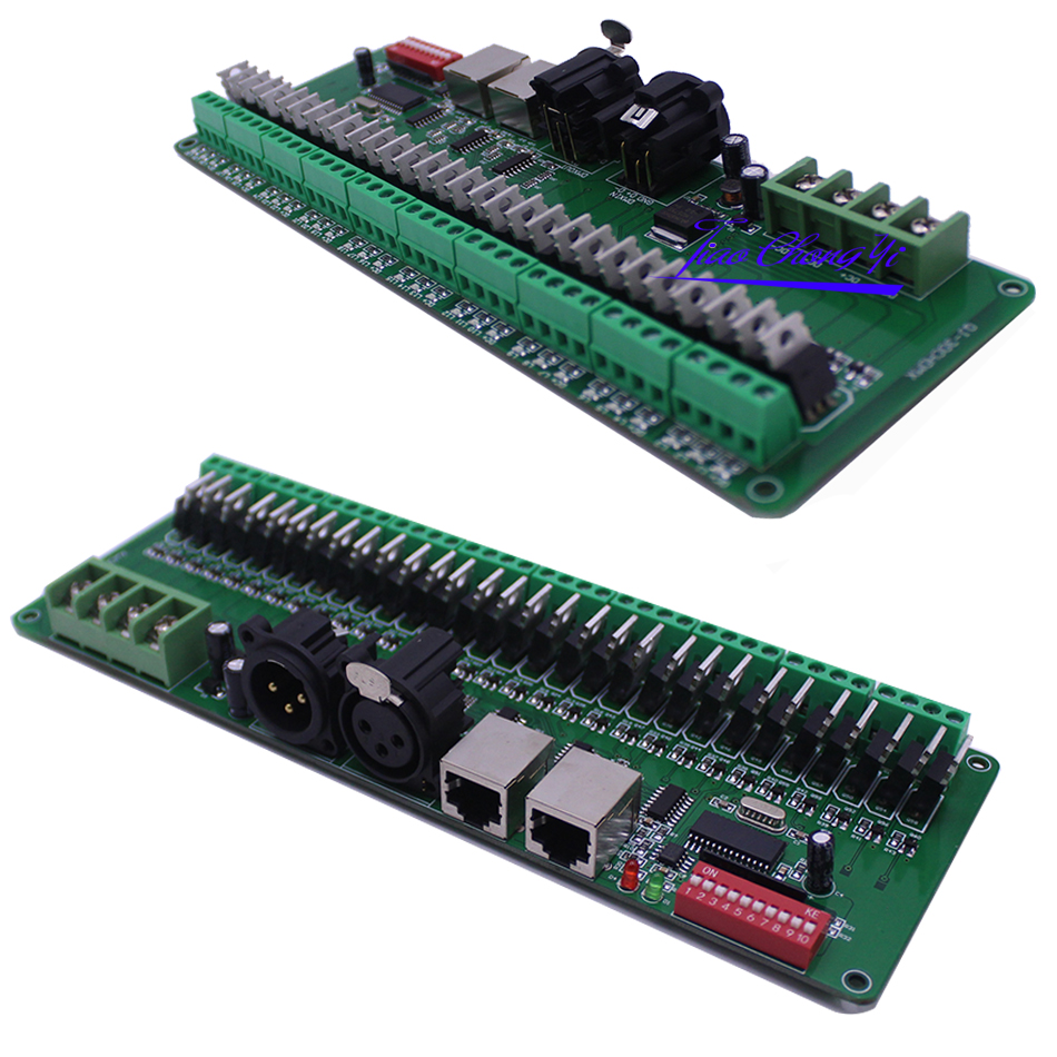
30CH-DMX512 Constant decoder Operation Instruction
Welcome to use the 30CH constant decoder, which take advantage of advanced microelectronic control technology. This technology changes the international fashion DMX512/1990 standard digital control signals into analog control signals. There are 1 ~ 30 output channels; each channel can achieve 256 control levels. This constant decoder is used when DMX512 control equipment control general LED lighting.
Products Performance:
Input Power: DC9V-DC24V
Maximum load current: 2A/CH×30
Maximum power load: 720W (12V) 1440W (24V)
Output gray level: 256
Input Signal: DMX512/1990
Output signal: 30 channels Constant PWM
Output DMX : 30 channels
standard XLR-3 caron plug
Size: L225*W80*H32
Gross Weight:300g
Basic functions:
There are 30 output channels, can connect with single or RGB lamps
0-100% dimming output, each channel 256 gray levels
International standard DMX512 input protocol, address code set by DIP switches;
Wide voltage DC input DC9V ~ DC24V;
Each occupied by 30 DMX address.
The decoder comes with 16 kinds of test patterns, 16 levels for rate of change
Decoder to use:
Note: FUN = OFF (the tenth code switch up) means to accept DMX512 signal mode
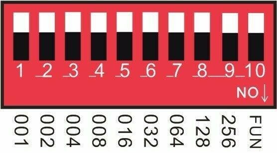
The first DMX address setting:
The
decoder set the address bit by coding switch, of which 1-9 is for
setting the start address of the Binary numeric code switch of DMX512,
the first one is the lowest position,
the ninth one is the highestBit of address code can be set to 255.
DMX512 start address code is the sum of switches 1-9, at the same time turn downside of the code switch (ON set to "1"), then the value of the bit can be gotten; coding switch
up (set to "0"), the value of the bit is 0.
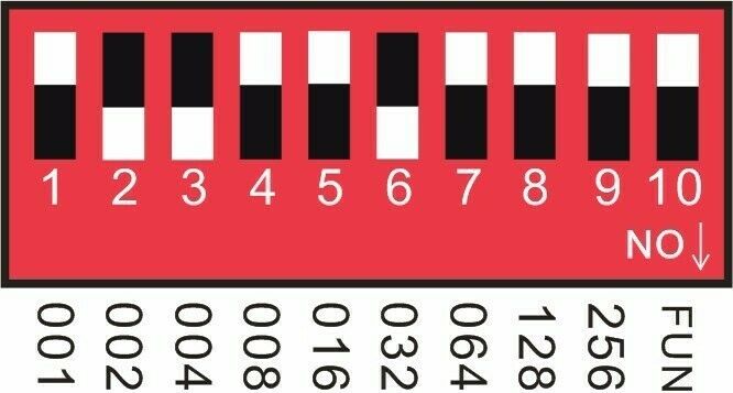
Example 1:
As
the following Schematic 1, DMX512 start address is set to 38, encoding
the No. 6,3,2 position on switch dial to "1", others set to "0", then
the sum of the switch 1-9 code value is
32 + 4 + 2, that is the DMX512 start address 38
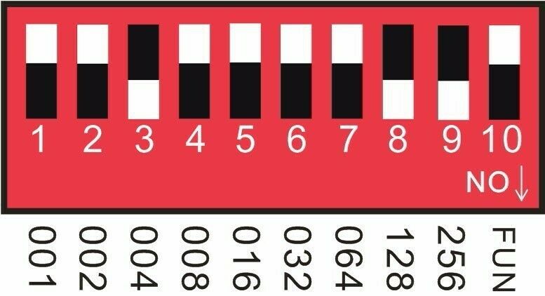
Example 2:
As the schematic 2, DMX512 start address is set to 388, encoding the no. 2,3,6,8 switch dial to "1", others set to "0",, then the sum of the switch 1-8 code value is 4 + 128 + 256 = 388,
that is the DMX512 start address 388.
Schematic 2
Operation instruction for the automat effect
Note: It will be Automatic operation mode when the No. 10 switch is turned down.
Effect choice (button switch No.1 to No.4):
1, Push No.1: Automat cycling.
2, Push No. 2: Seven-color gradual cycle changing.
3. Push No.1 &2: RGB Fade in and out
4. Push No.3: Severn color jumping
5. Push No.1 & 3: RGB jumping.
6. Push No.2 & 3: Red color.
7. Push No. 1 & 2 & 3:Green color.
8. Push No.4: Blue color.
9. Push No.1 & 4: Yellow.
10: Push No.2 & 4: Violet.
11. Push No.1 & 2 & 3: Cyan.
12. Push No.3 & 4: white.
13. Push No.1 & 3 & 4: Seven-color gradual cycle changing and jumping.
14. Push No.2 & 3 & rgb-color gradual cycle changing and jumping.
15. Push No.1 & 2 & 3 & 4: Seven-color jumping and rgb-color jumping.
Speed Choices (Button Switch No.5 to No. 8)
1. Push No.5: 0.5 second. 2. Push No.6: 1 second. 3. Push No.7: 1.5 second. 4. Push No.8: 2 second.
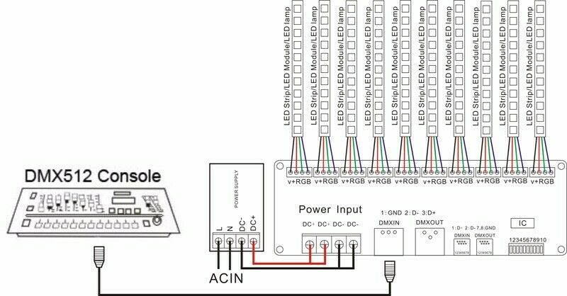
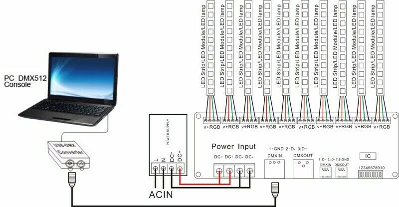
Schematic for System Connection:
DMX512 Console + 30CH DMX deocder
Plan two:PC DMX512 Console + USB DMX controller + 30CH DMX deocder
Installation Notes:
1 This kind of controller works only under DC9V-24V, which is provided by the matched controllable main power, or else the controller will be damaged.
2 The UTP wire is connected hand in hand to make the cable, when two or more controller connected.
3 The power supply should be off when connecting the electric wires, and it can be turned on till making sure the wires are connected correctly and the indicator of main power in red is lighting.
4 Controller should work under the environment of adequately ventilated, dry, not corroded, no flammable gas and rust.
5 Please check the wires connection regularly so that the wires of aged, rust-eaten, and damaged insulation spacer can be replaced timely
Simple troubleshooting and maintenance:
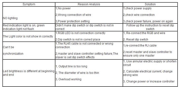
FAQ: