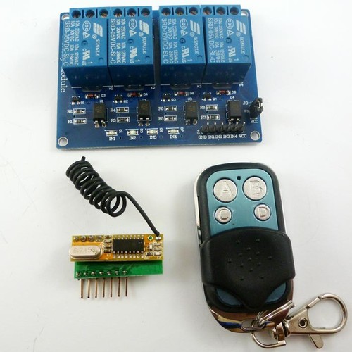
1 PCS DC5V 4 Channel Arduino Relay Board;
| Receiver module | UNO/MEGA2560 |
| GND | GND |
| VCC | 13 |
| I0 | 12 |
| I1 | 11 |
| I2 | 10 |
| I3 | 9 |
| VT | 8 (You can ignore) |
//Author: cantone-electonics
//More information welcome to :
//Arduino 1.0.4
//Arduino uno R3
//Arduino 4 channel Wireless Controller
int VCC = 13;//
int I0 = 12;
int I1 = 11;
int I2 = 10;
int I3 = 9;
int VT = 8;
int Relay1 = A0;
int Relay2 = A1;
int Relay3 = A2;
int Relay4 = A3;
int InputState = 1; // variable for reading the input status
// the setup routine runs once when you press reset:
void setup() {
// initialize the digital pin
pinMode(VCC, OUTPUT);
pinMode(I0, INPUT);
pinMode(I1, INPUT);
pinMode(I2, INPUT);
pinMode(I3, INPUT);
// pinMode(VT, INPUT);
pinMode(Relay1, OUTPUT);
pinMode(Relay2, OUTPUT);
pinMode(Relay3, OUTPUT);
pinMode(Relay4, OUTPUT);
digitalWrite(Relay1, HIGH);
digitalWrite(Relay2, HIGH);
digitalWrite(Relay3, HIGH);
digitalWrite(Relay4, HIGH);
digitalWrite(VCC, HIGH);//AS VCC
//Activate input pin internal pull-up resistors
digitalWrite(I0, HIGH);
digitalWrite(I1, HIGH);
digitalWrite(I2, HIGH);
digitalWrite(I3, HIGH);
// digitalWrite(VT, HIGH);
delay(2000);//Waiting for rf receiver module startup
}
// the loop routine runs over and over again forever:
void loop() {
InputState = digitalRead(I0);
if(InputState==0) digitalWrite(Relay1, HIGH); else digitalWrite(Relay1, LOW);
InputState = digitalRead(I1);
if(InputState==0) digitalWrite(Relay2, HIGH); else digitalWrite(Relay2, LOW);
InputState = digitalRead(I2);
if(InputState==0) digitalWrite(Relay3, HIGH); else digitalWrite(Relay3, LOW);
InputState = digitalRead(I3);
if(InputState==0) digitalWrite(Relay4, HIGH); else digitalWrite(Relay4, LOW);
}