Typical applications

1 Motor reversing control circuit,Power supply is DC 5V ,Wiring diagram below. "LOAD" may be DC 1-110V OR 85-265V AC/DC Motor

2 Live wire and Netural wire control circuit,Power supply is DC 5V ,Wiring diagram below. "LOAD" may be AC 85-265V equipment


Product Name: DC5V 2 Channel Multi-function Delay Cyclic Timer Relay Control Motor Reverse LED
      
 
Module No.: KC22B02_5V
    
Package inlcuded:
1 PCS DC 5V 2 channel multi-function delay relay board


Description:
 
DC 5V 2 channels 0-9999 seconds multi-function delay relay board
Nine kinds of functions can be switched
Products can set the delay time and Function.After setting up, power-up setting value is previous setting delay time and Function as we set last time (power-down memory function);
 
Size: 75mm × 35mm x 20mm
Weight : 35g
Relay maximum load capacity: DC 1-110V/6A; AC 85-250V/5A


User Manua:
 
Noun resolved:
 
COM : Common terminal
 
NO: Normal open
 
NC: Normally Close
 
Relay close: COM connect NO,COM disconnect NC
 
Relay open : COM disconnect NO,COM connect NC
 
 
Function mode :

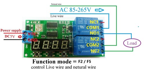
F1 After power on. Relay 1 close,relay 2 open, delay time is T1. Then relay 1 open,relay 2 is close. Delay time is T2.Relay 1 close, relay 2 open, delay time is T1.Such repeated cycles of action...(for Motor reversing)

F2 After power on.Relay 1 close, relay 2 close, delay time is T1. Then relay 1 open, relay 2 is open. Delay time is T2 . Relay 1 close , relay 2 close, delay time is T1. Such repeated cycles of action...

F3 After power on . Relay 1 close , delay time is T1. Then relay 1 open , Delay time is T2 . Relay 1 close,delay time is T1. Such repeated cycles of action... ,Relay 2 never work .

F4 After power on . Relay 2 open , delay time is T1. Then relay 2 close, Delay time is T2 . Relay 2 close , delay time is T1. Such repeated cycles of action... ,Relay 1 never work .
 

F5 After power on . Relay1 and relay 2 close, delay time is T1.Relay1 and relay 2 open (control Live wire and netural wire)

 
F6 After power on . Relay 1 close , delay time is T1. Then relay 1 open,Relay 2 never work .
 
F7 After power on . Relay 2 no action, delay time is T1. Then relay 2 close, Relay 1 never work .


F8 After power on. Relay 1 and Relay 2 both close, delay time is T1. Then relay 1 open,Delay time is T2, relay 2 open.


F9 After power on . Relay 1 and Relay 2 both open , delay time is T1. Then relay 1 close, Delay time is T2, relay 2 close.
 
 
Function Mode Switch:
Keep pressing K1, press K2 to switch Function mode
  
F5 F6 F7 mode has only 1 delay time counter (T1), the other mode has two delay time counters (T1 T2); Keep pressing K1 ,press K3, switch T1 T2 counter .


Adjustment delay time :
  
Press K2, switching 4 bits of delay time counter(0000~9999S),the selected bit flash , press K3 to adjusted counter . Repeat to switch the rest bits .
 
After switching all bits ,then press K2 exit adjustable delay mode; or press K1, exit adjustable delay mode; or wait 10 seconds exit adjustment mode
  
 
Display way :
  
Keep pressing the K3 for 5 seconds , the digital display Turn off. Keep pressing K3 5 second more (or re-power), the digital display Turn on .
  
F5 F6 F7 F8 F9 mode, the delay counter is completed, digital display Turn off, enter a low-power mode, press K1, exit the low-power mode