|
This item includes: 1 pc Stepper motor driver DM2722A, 110-230VAC, peak 9.8A, 200 micsteps Stepper motor driver DM2722A
Detailed information:
|
FEATURES
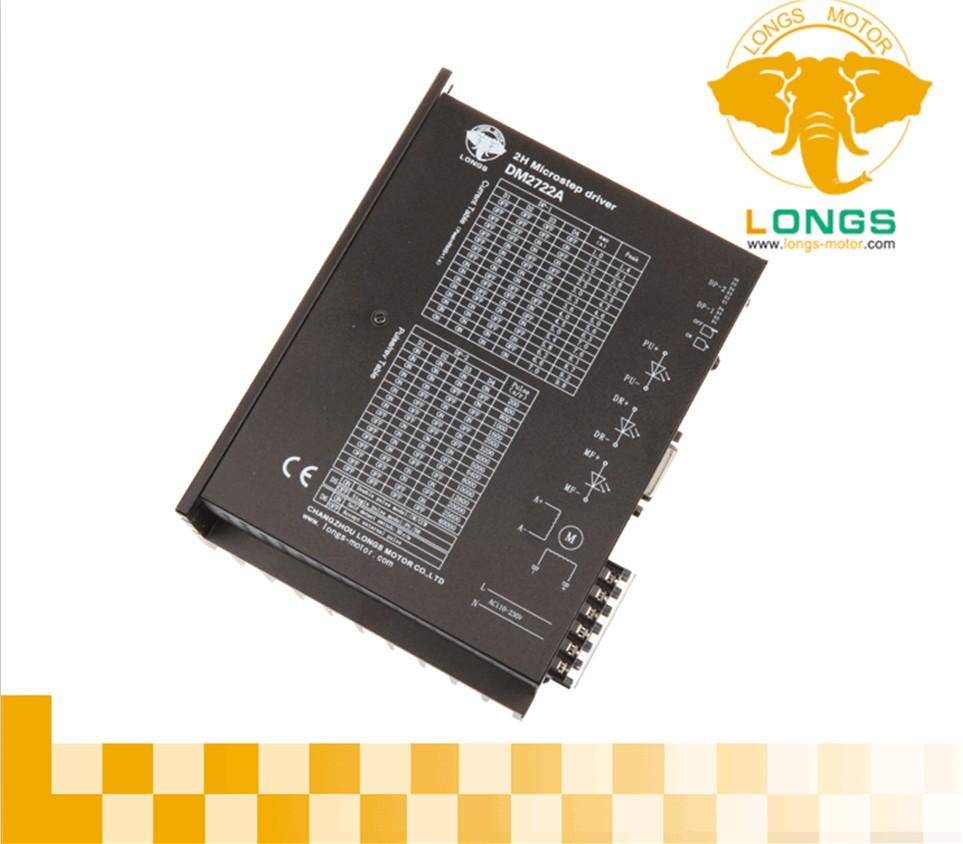
DM2722A is a new-generation digital 2-phase stepper motor driver based on DSP control. The driver combines advanced DSP control technique and unique control circuit. The driver voltage is AC110-230V and driver current is below 7.0A. The driver can be used for types of 2-phase stepper motor with external diameter 86-130mm. The driver adopts circuit similar to servo control, so the motor can run smoothly with little vibration and noise. And the maximum positioning accuracy could reach 40,000 steps/rev. The product is widely used in big and medium-sized CNC equipment with higher resolution, such as engraving machine, medium-sized CNC machine tool, computer-controlled embroidery machine, packing machine, etc.
● High performance, low price
● The driver features 16-grade micro-stepping with equal angular degree and constant torque; the highest resolution may reach 40,000 steps/rev.
● The highest response frequency can reach 500Kpps
● When the step-by-step impulse has halted for over 100ms, the coil current will automatically reduce to half of the set value, to effectively reduce motor warming.
● Photoelectric isolation signal input/output
● Driver current from 1.0A / phase to 7.0A / phase, adjustable with 16 grades
● Single power input, voltage range: AC 110V to 230V
● Phase memory function (when the input has stopped unexpectedly or powered off, the driver will automatically memorize motor phase at that time.)
● I/O signal, the driver uses photoelectric isolation technique and signal level is 5V ~ 24V, compatible
● Function of pulse smooth technique makes the motor run stably at low speed. The level of smooth can be adjusted.
It features motor inductance adjustment function, giving full play to the adaptive motor.
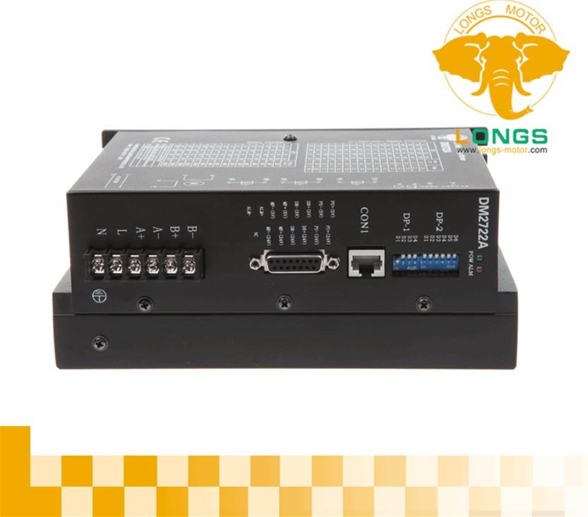
Port Function
|
Current & Micro-step Setting |
Current setting
The working current of the driver is set by DIP-1 terminal, the working current is normal working output current (note: the current is effective current)
|
1.0 |
1.5 |
2.0 |
2.3 |
2.5 |
3.0 |
3.3 |
3.6 |
4.0 |
4.5 |
5.0 |
5.4 |
5.8 |
6.2 |
6.6 |
7.0 |
|
|
D1 |
OFF |
OFF |
OFF |
OFF |
OFF |
OFF |
OFF |
OFF |
ON |
ON |
ON |
ON |
ON |
ON |
ON |
ON |
|
D2 |
OFF |
OFF |
OFF |
OFF |
ON |
ON |
ON |
ON |
OFF |
OFF |
OFF |
OFF |
ON |
ON |
ON |
ON |
|
D3 |
OFF |
OFF |
ON |
ON |
OFF |
OFF |
ON |
ON |
OFF |
OFF |
ON |
ON |
OFF |
OFF |
ON |
ON |
|
D4 |
OFF |
ON |
OFF |
ON |
OFF |
ON |
OFF |
ON |
OFF |
ON |
OFF |
ON |
OFF |
ON |
OFF |
ON |
The micro-step is set by DIP-2 with 16 levels. The first 4 dip of DIP-2 is for micro-step setting and the last 2 dip is for function setting.Micro-step setting
The attached table: steps (pulse/rev)
|
|
|
Possible problems & Solutions |
|
Possible reason |
Measure |
|
|
Motor not run |
No light with “POW” or ”ALM” indicator light |
To check if the power supply is normal |
|
“ALM” indicator light is on |
To check overcurrent or overheating, motor missing |
|
|
The motor shaft is locked, the motor cannot operate. |
To check external control signal |
|
|
Indicator light shows normal, and the motor shaft is unlocked |
To check if MF signal is active |
|
|
Motor blocked |
The max speed is set too high |
To lower the max speed |
|
The time for speeding up is too short |
To lengthen the time or increase the pulse filtering constant of the driver |
|
|
Inaccurate position |
The micro-stepping number is not correct |
To select the correct micro-stepping number |
|
Excessive load for the motor |
To replace the motor or moderately increase running current of the driver |
|
|
"Leakage" phenomenon |
The driver and motor is not reliably grounded |
To reliably ground the driver and the motor |
|
Severe warming of the driver and the motor |
Large running current of the driver or bad external thermal conditions |
To moderately reduce driver running current or improve ventilation of the driver and the motor |
|
Caution |
1 The input voltage is lower than AC270V.
2. Falling edge is effective of input pulse signal. If you need the rising edge to be effective, please set inner parameter of the driver.
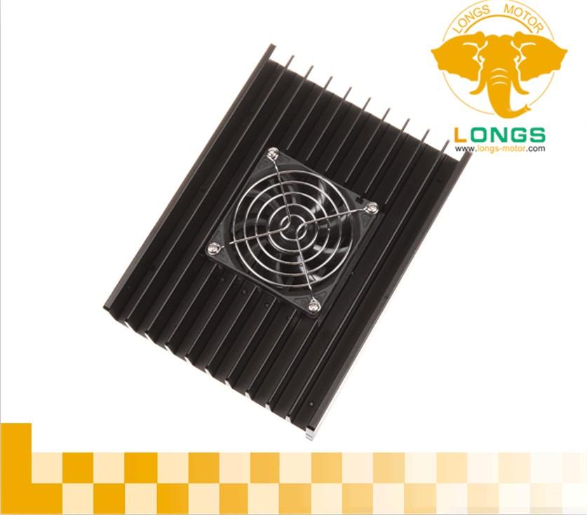
3. When the driver temperature goes beyond 75 degrees, it will halt working, and the fault indicator ALM will be on. Until the temperature drops to 50 degrees, the driver may resume work after a second-time power-on. In case of such overheat protection, please install heat sink.
4. In case of overcurrent (short circuit of load), the fault indicator ALM will be on. Please check motor wiring and other fault of short circuit; after the fault is removed, it will resume upon a second-time power-on.
5. In case of no motor, the fault indicator ALM will be on. Please check motor wiring; after the fault is removed, it will resume upon a second-time power-on.