【USA Stock】
For CNC Router Engraving Milling Machine
Good News:
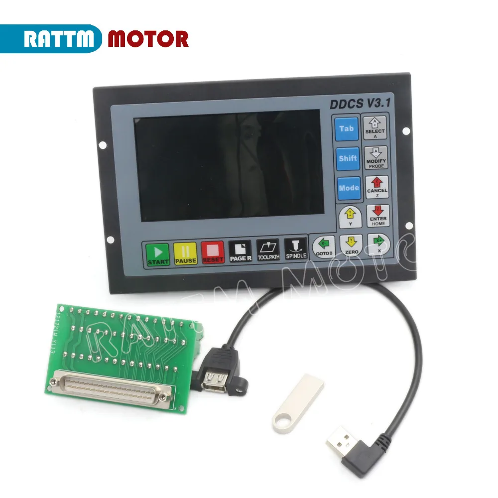
Package include:
Descriptions: |


 DDCS V3.1 Brief technical feature:
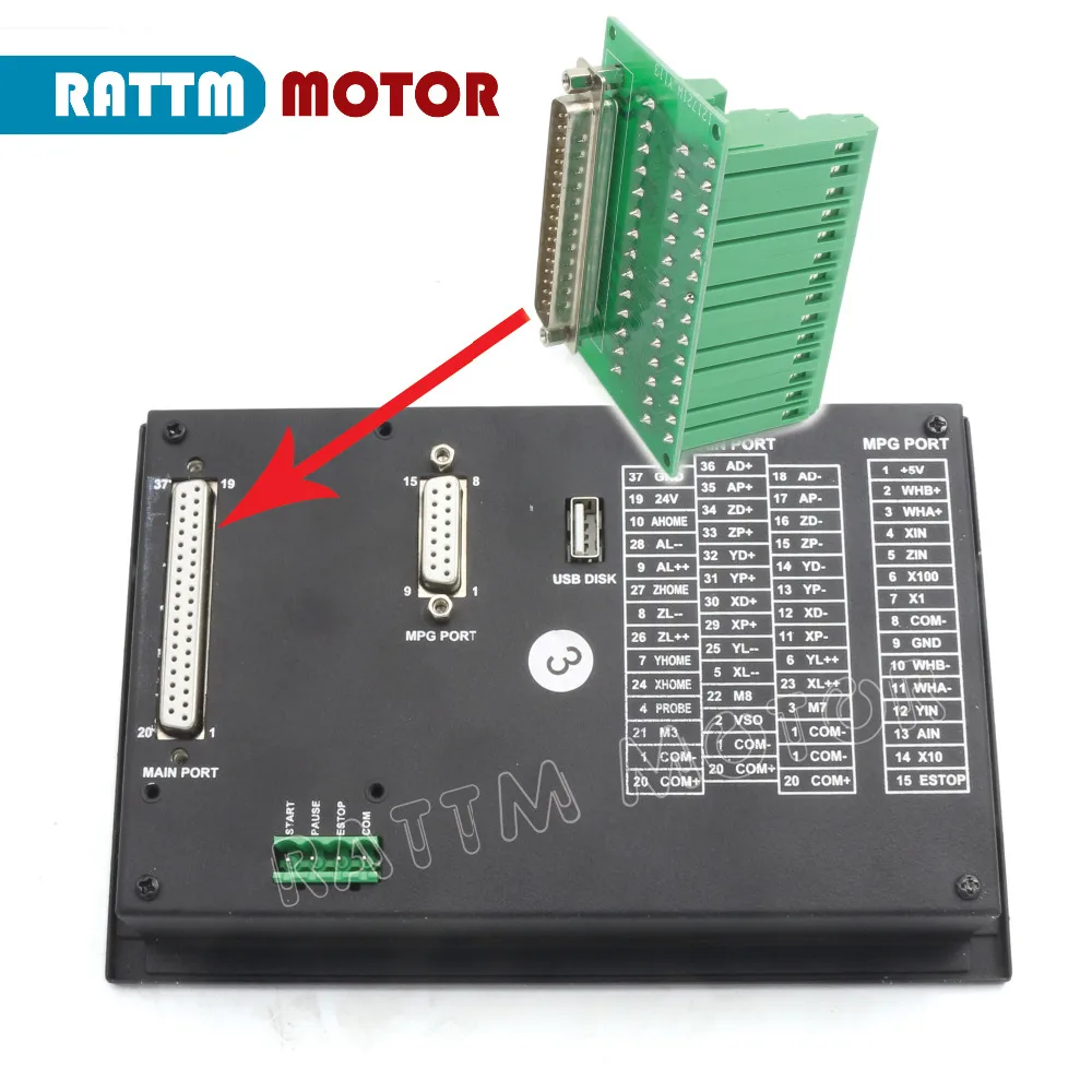
|
|
|
|---|


The Limit wiring at X++ direction with mechanical limited switch
Power Supply Input
Spindle control output
|
|
|
|---|


Stepper/Servo Control Output
The Limit wiring at X++ direction with 3-line proximity switch
The Probe Wiring
Outward Appearance,Structure and Size

- The DDCS V3.1 is a small box that can fit in a window of a small control box or control cabinet.
- To mount the unit in an equipment c abinet, cut the hole182.5mm*59mm
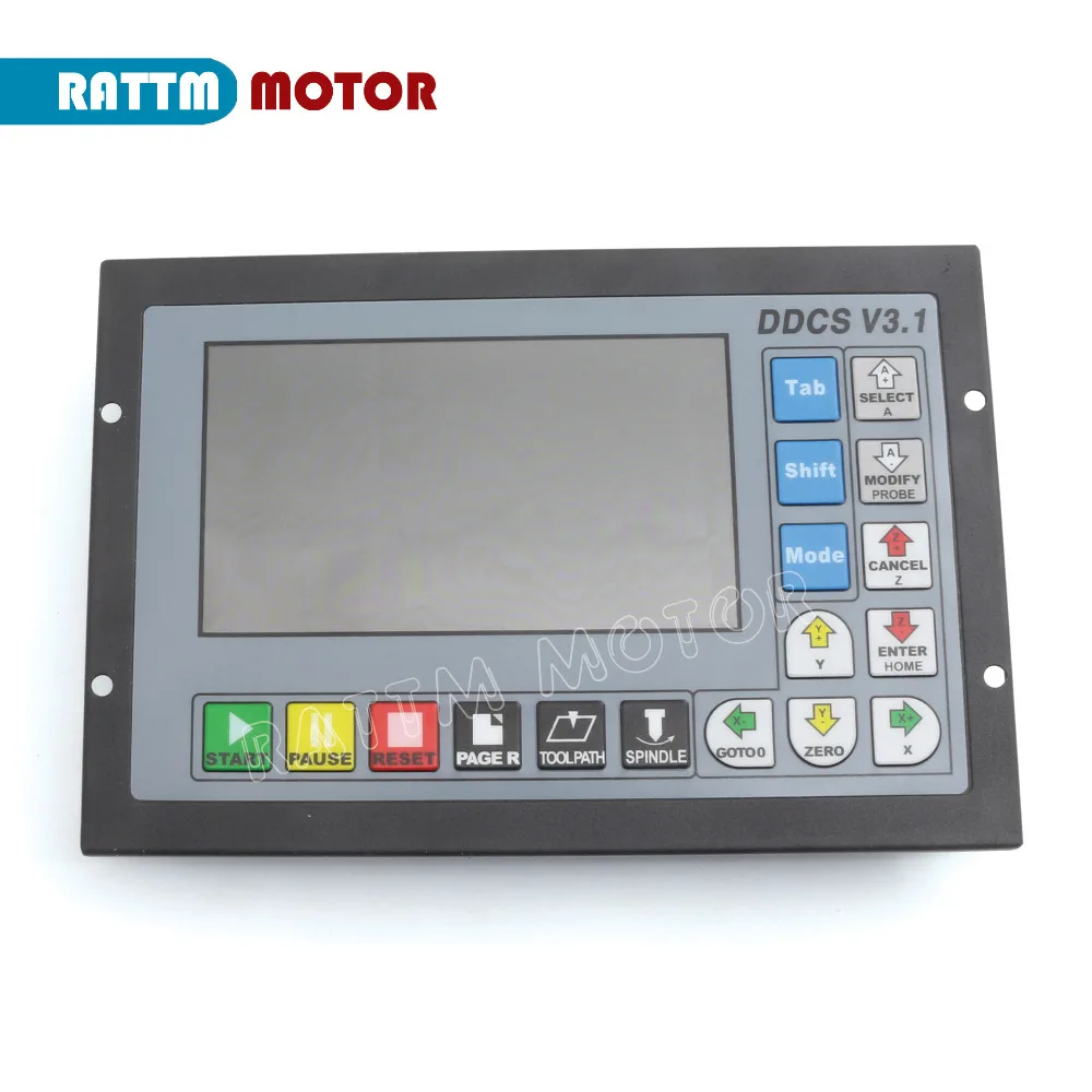
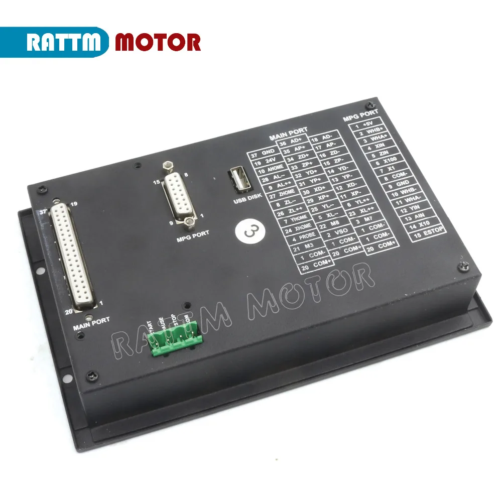
- The front of the product is 17 user keys and 4.3" and 480*272 LSD (Liquid Crystal Display), and the reverse side is input signal, spindle control, stepper/ servo control, MPG and other four sets of interfaces as well as USB interface and power interface.
- The front panel is 191mm*128mm*5mm
- The main body is 191mm*128mm*37mm
- The back panel is 175mm*110mm
- Control System Unit is compatible with Metric Units and Imperial Units;
- MPG and extended Keyboard can also control and edit the controller system
- 3 kinds Probing Modes:Fixed Position of tool sensor,Floating Position of the tool
- Added a lot of parameters,Optimal Design and algorithm
- Cited the new circuit design and metal box,which can avoid the noise a lot
- The DDCS V3.1 is a small box that can fit in a window of a small control box or control cabinet.
- To mount the unit in an equipment c abinet, cut the hole182.5mm*59mm
- The front of the product is 17 user keys and 4.3" and 480*272 LSD (Liquid Crystal Display), and the reverse side is input signal, spindle control, stepper/ servo control, MPG and other four sets of interfaces as well as USB interface and power interface.
- The front panel is 191mm*128mm*5mm
- The main body is 191mm*128mm*37mm
- The back panel is 175mm*110mm
- Control System Unit is compatible with Metric Units and Imperial Units;
- MPG and extended Keyboard can also control and edit the controller system
- 3 kinds Probing Modes:Fixed Position of tool sensor,Floating Position of the tool
- Added a lot of parameters,Optimal Design and algorithm
- Cited the new circuit design and metal box,which can avoid the noise a lot
4 Axis MPG Pendant Handwheel with Emergency stop with 15-pin plug

Description:
1.The
CNC 4 Axis handheld controller MPG Pendant with x1, x10, x100
selectable, You are bidding one complete unit of the MPG pendant with
Emergency stop for 4 axis CNC machine, it equipped with our popular
machined MPG unit with 4 axis and scale selector, LED indicator also
send feedback from the CNC machine to user about the status of the unit. 2.All
Wiring isolated from MPG unit and provide a easy to install wiring
diagram, it suit both commercial machine as a replacement jog control
unit or other computer based controller. Which add great control
flexibility to the system. Specification:1. x1, x10, x100 switch2. X,Y,Z,4th axis selector switch3. LED indicator4. With Emergency stop5. High quality professional chassis6. 6ft extendable high quality shielded cable cord7. Magnetic base holder can place anywhere on the machine steel surface8. Required 5V+, 150mA, power for MPG9. Phase output is A ,/A and B,/B;10. TTL output, drive capability +-20mA;11.
Support CNC system:Taiwan Pou Yuen M600 M500 M520i T300 series,
Higerman, HANUC,GSK,opened NC, KND,Siemens, the NUM, Spain FAGOR (NEW,
8055I) and so on.12.Wiring:User can wire this unit to the CNC system with easy.
Description:
1) CNC
system and position control of various mechanical devices, mainly for
CNC machine tools and various mechanical zero correction and signal
division.
2) 100 times per revolution slightly
cracking point,100 pulses per revolution output, holding the handle of the panel and all-metal high-grade design.
3) Metal code disc, high precision, good texture
4) Easy installation, shaped thin, ultra-light.
5) DC 5V power system
6) Voltage, single-ended, differential in three output options provide 100PPR pulse output options.
7) Driver output type, anti-interference ability, long-distance transmission.
8) Oil, water, dust-proof design (grade IP65) spiral stretch 20 million guaranteed.
Features:
1) Novelty, easy to move, interference, load capacity.
2) Full plastic shell, insulation, high strength, anti-oil seal design.
3) With × 1, × 10, × 100 third gear ratio, enabling 4-12 axis magnification switch
4) With the control switch, emergency stop switch optional, easy to operate
5) For CNC machine tools, printing machinery, numerical control equipment
Specification:
Resolution 100PPR Supply Voltage DC5V +/-5% Supply Current ≤80mA Output Voltage ≥2.5V ≤0.4V Output Current <40mA Fall/Rise time ≤5ns(typ) Switch X1,X10,X100 Axis Switch OFF,X,Y,Z,4 Response Frequency 0-10KHz Weight 560g
Description:
Description:
1) CNC system and position control of various mechanical devices, mainly for CNC machine tools and various mechanical zero correction and signal division.
2) 100 times per revolution slightly
cracking point,100 pulses per revolution output, holding the handle of the panel and all-metal high-grade design.
3) Metal code disc, high precision, good texture
4) Easy installation, shaped thin, ultra-light.
5) DC 5V power system
6) Voltage, single-ended, differential in three output options provide 100PPR pulse output options.
7) Driver output type, anti-interference ability, long-distance transmission.
8) Oil, water, dust-proof design (grade IP65) spiral stretch 20 million guaranteed.
Features:
1) Novelty, easy to move, interference, load capacity.
2) Full plastic shell, insulation, high strength, anti-oil seal design.
3) With × 1, × 10, × 100 third gear ratio, enabling 4-12 axis magnification switch
4) With the control switch, emergency stop switch optional, easy to operate
5) For CNC machine tools, printing machinery, numerical control equipment
Specification:
| Resolution | 100PPR |
| Supply Voltage | DC5V +/-5% |
| Supply Current | ≤80mA |
| Output Voltage | ≥2.5V |
| ≤0.4V | |
| Output Current | <40mA |
| Fall/Rise time | ≤5ns(typ) |
| Switch | X1,X10,X100 |
| Axis Switch | OFF,X,Y,Z,4 |
| Response Frequency | 0-10KHz |
| Weight | 560g |
