DDCSV3.1 CNC Offline Controller 4 Axis Nema34 Stepper Motor Closed Loop Driver
for CNC Router Engraving Milling Machine
【Ship from Germany Warehouse to EU Countries!!!】
【Fast Shipping to EU Customers】
Package included:
- 3 x 86HSE118 Nema34 8N.m Servo Motor Closed Loop 118mm 6A
- 3 x 2HSS86 Servo Driver
- 3 x 3M extension wire
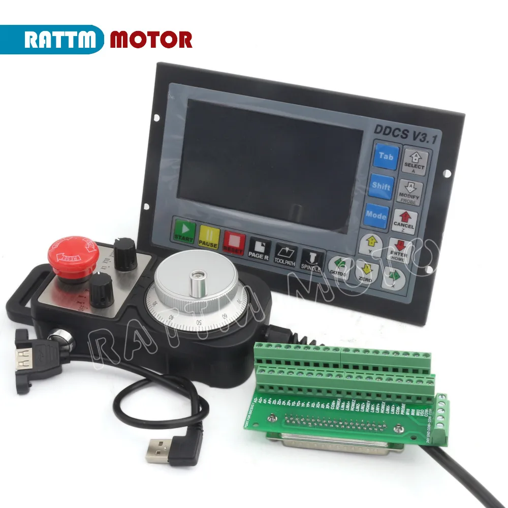
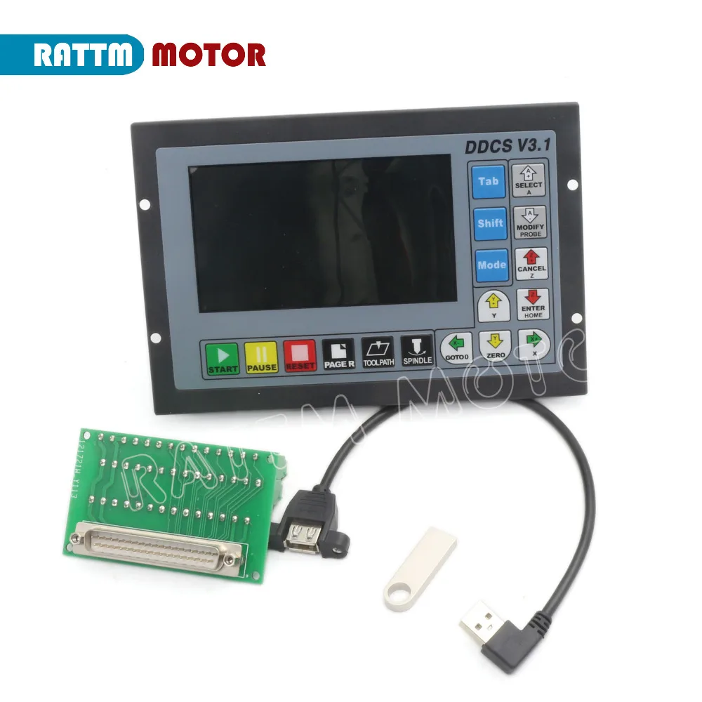
- 1 x 4 Axis Motion Offline Controller DDCSV3.1
- 1 x Handwheel MPG with emergency stop
- 1 x 4GB USB Flash drive
- 1 x USB Extension Cable+Accessories
- English user manual will send by email
100% Brand New and High Quality!
Nema34 8N.m Closed Loop Servo Stepper Motor & 2HSS86 Servo Driver CNC Kit

Package include:
- 1 x 86HSE118 Nema34 8N.m Closed-loop servo motor 86x86x118mm
- 1 x 2HSS86 Servo driver
- 1 x 3M Extension cord
- Pdf. user manual (If you have not received the user manual at Amazon Message Center from us,please message us)

Specifications
- Size:86x86x118mm
- Current :6.0A
- Phase:2
- Step Angle(degrees):1.8 degree
- Lead wire:4pcs
- Holding Torque:8N.m
- Resistance:0.44±10%Ω
- Inductance:3.7±20%mH
- Insulation resistance:100MOhm(500V DC)
- Insulation Class:B


Overview
- This is the nema 34 series hybrid stepper servo kit. The 2HSS86 driver adopts new generation 32 bit DSP and vector control technology, which can avoid the stepper motor losing steps and ensure the accuracy of the motor.
- The torque reducing is much lower than open loop stepper motor when it is at higher speed. The high speed performance and torque are enhanced in a great extent. Meanwhile the current control is based on the load, that can reduce the motor temperature rising effectively, then can extend the using life of the motor.
- The build-in place in position and alarm output signal can help the upper monitor to monitor and control. The function of position ultra difference alarm can ensure the machine work safely. The closed loop system is an ideal improvement and a good replacement of open loop system,besides that,it also have some function of AC servo motors.
Package include:
- 1 x 86HSE118 Nema34 8N.m Closed-loop servo motor 86x86x118mm
- 1 x 2HSS86 Servo driver
- 1 x 3M Extension cord
- Pdf. user manual (If you have not received the user manual at Amazon Message Center from us,please message us)
Specifications
- Size:86x86x118mm
- Current :6.0A
- Phase:2
- Step Angle(degrees):1.8 degree
- Lead wire:4pcs
- Holding Torque:8N.m
- Resistance:0.44±10%Ω
- Inductance:3.7±20%mH
- Insulation resistance:100MOhm(500V DC)
- Insulation Class:B
Overview
- This is the nema 34 series hybrid stepper servo kit. The 2HSS86 driver adopts new generation 32 bit DSP and vector control technology, which can avoid the stepper motor losing steps and ensure the accuracy of the motor.
- The torque reducing is much lower than open loop stepper motor when it is at higher speed. The high speed performance and torque are enhanced in a great extent. Meanwhile the current control is based on the load, that can reduce the motor temperature rising effectively, then can extend the using life of the motor.
- The build-in place in position and alarm output signal can help the upper monitor to monitor and control. The function of position ultra difference alarm can ensure the machine work safely. The closed loop system is an ideal improvement and a good replacement of open loop system,besides that,it also have some function of AC servo motors.
2HSS86 Driver


- Voltage range: AC24-70V or DC30-100V
- Peak current :Peak 8.0A
- Logic input current:7-20mA
- Frequency:0-200KHz
- Suitable motor: 86HSE156, 86HSE118, 86HSE82
- Encoder lines:1000
- Insulation resistance:>=500MΩ
- Operating temprature:0~50℃
- Operating humidit:40~90%RH
- Virbration:5.9m/s2Max
1.2.1 Stepper motor closed loop system, never lose step.
1.2.2 Improve motor output torque and working speed.
1.2.3 Automatic current adjustment based on load
1.2.4 Suitable for all mechanical load conditions (include low rigidity belt pulley and wheel), no need to adjust gain parameter.
1.2.5 Drive nema 34 series closed loop stepper motor.
1.2.6 Pulses response frequency can reach 200KHZ
1.2.7 16 kinds microsteps choice, highest 51200microsteps/rev.
- Over-current,over-voltage and position ultra difference protection function.
- Closed loop stepper system can be applied to all kinds small automatic equipment and instrument. Such as engraving machine, special industrial sewing machine, stripping machine, marking machine, cutting machine, graph plotter, cnc machine, automatic assembly equipment and so on
|
|
|
|---|---|---|
| 1.2.1 Stepper motor closed loop system, never lose step. 1.2.2 Improve motor output torque and working speed. 1.2.3 Automatic current adjustment based on load 1.2.4 Suitable for all mechanical load conditions (include low rigidity belt pulley and wheel), no need to adjust gain parameter. 1.2.5 Drive nema 34 series closed loop stepper motor. 1.2.6 Pulses response frequency can reach 200KHZ 1.2.7 16 kinds microsteps choice, highest 51200microsteps/rev. |
|
Wiring diagram

4 Axis Offline Controller with MPG

1.Digital Dream is a numerical control company specializing in the research, development and production of various CNC (Computer Numerical Control) systems since 2008. Digital Dream
2.aims to combine high quality and high reliability with affordability. The DDCS is a 3~4 axis motion controller for stepper and servo systems. DDCS V3.1 is updated from DDCS V2.1 on software and hardware.We are very proud of this product, it combines .great power with a tiny footprint and is easy to use. After a very short time you will be familiar with the functions and this manual will help you.
3.The highest output pulse per axis is 500KHz. This provides high control precision for stepper motors and servo motors.
4.The DDCS numerical control system adopts the ARM+FPGA design framework. ARM controls the human-computer interface and code analysis and the FPGA provides the underlying algorithms and creates the control pulse. This guarantees reliable control and easy operation.
5.The internal operating system is Linux based. The panel layout structure of the DDCS V3.1 is very rational to save space. All operations are controlled by only 17 keys and a comprehensive G code set is supported. The DDCS can be used for many styles and types of CNC machines. Lathes, Routers, Pick and Place and Mills are just a few examples. The DDCS operates as a Stand Alone system without the need of a computer. This guarantees high precision, accuracy and reliability. The interface, even very comprehensive, can be learned in a very short time.
6.Digital Dream Standalone Motion Controller DDCS V3.1 Page -4 DDCS V3.1 Users Manual 1.2 DDCS V3.1 Brief technical feature
1.1 Introduction
DDCSV3.1 is the 4 axis motion controller which has been researched and developed by Faster CNC for four years. The control period of each position is only 4 milliseconds, with a high control precision. The highest uniaxial output pulse is 500KHz and the pulse width can be adjusted. It supports the common stepper motor and servo motor.
DDCSV3.1 numerical control system adopts the ARM+FPGA design framework. The ARM can finish the part of human-computer interface and code analysis and the FPGA can finish the part of underlying algorithm and control pulse generate, with the reasonable design, reliable control and easy operation.
The panel layout structure of DDCSV3.1 is rational. The CNC MOTION SYSTEM Controller can be finished only by 17 keys and it supports the FANUC with high universality to be compatible with G code set.
This manual introduces the operation method of the DDCSV3.1,the machine tool and the operation procedure of the machine tool. By lots of graphical representation and examples, the uses can quickly learn to use the DDCSV3.1 CNC system.
DDCS V3.1 Brief technical feature:
1) 16 photoelectric isolated digital inputs,3 photoelectric isolated digital outputs;
2) 3.1 Version enhenced Algorithm,support soft interpolation,fixed arc interpolation bug of the old version;
3) Analog spindle control 0-10V spindle control (can be modified as PWM output);
4) 3-4 axis motor Control.Differential Pulse and direction output signal,Max.500Khz per axis;
5) ARM9 main control chip,FPGA core algorithm chip;
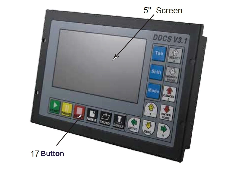
6) 5 inches TFT screen, resolution ratio: 480x272,17 operation keys;
7) The Power Supply for the controller is 24VDC, minimum Current is 0.5A;
8) The Power Supply for IO Port is 24VDC,minimum current is 0.5A;By the IO power supply,system already supply the power for IO ports.So no need the external power supply for IO port anymore;
9) USB flash disk support for G code file input,no size limited of the G-code file ;
10) Support standard MPG;
11) Jog function for each axis (continuous, step, defined distance);Customer can define the distance;
12) Support the operation of quickly specify the running position;
13) Support for “Power Cut” recovery. Data is automatically saved;
14) The controller only support NPN type limited switch.
1.3 Outward Appearance, Structure and Size
The DDCS V3.1 is a small box that can fit in a window of a small control box or control cabinet.
Four locking hooks fix this controller from the frame.
The front panel is 191mm*128mm*5mm;
The main body is 191mm*128mm*37mm;
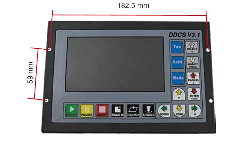
To mount the unit in an equipment c abinet, cut the hole182.5mm*59mm
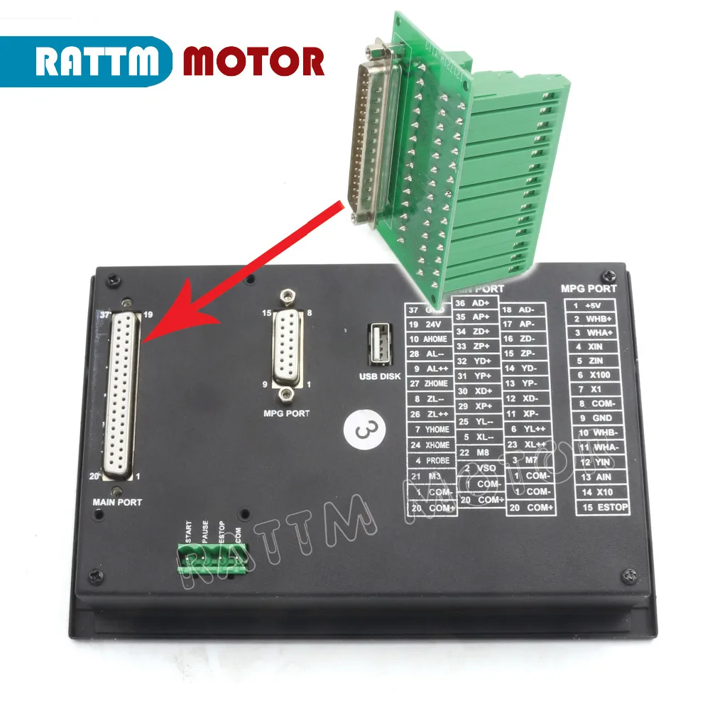
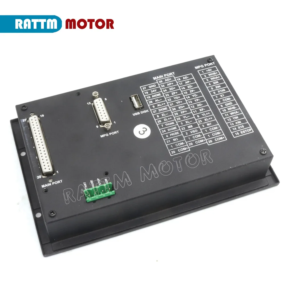
The front of the product is 17 user keys and 1 4.3’’and 480*272 LSD (Liquid Crystal Display), and the reverse side is input signal, spindle control, stepper/ servo control, MPG and other four sets of interfaces as well as USB interface and power interface. Please look at the reference picture 1-3 and picture 1-4 in detail.


1.Digital Dream is a numerical control company specializing in the research, development and production of various CNC (Computer Numerical Control) systems since 2008. Digital Dream
2.aims to combine high quality and high reliability with affordability. The DDCS is a 3~4 axis motion controller for stepper and servo systems. DDCS V3.1 is updated from DDCS V2.1 on software and hardware.We are very proud of this product, it combines .great power with a tiny footprint and is easy to use. After a very short time you will be familiar with the functions and this manual will help you.
3.The highest output pulse per axis is 500KHz. This provides high control precision for stepper motors and servo motors.
4.The DDCS numerical control system adopts the ARM+FPGA design framework. ARM controls the human-computer interface and code analysis and the FPGA provides the underlying algorithms and creates the control pulse. This guarantees reliable control and easy operation.
5.The internal operating system is Linux based. The panel layout structure of the DDCS V3.1 is very rational to save space. All operations are controlled by only 17 keys and a comprehensive G code set is supported. The DDCS can be used for many styles and types of CNC machines. Lathes, Routers, Pick and Place and Mills are just a few examples. The DDCS operates as a Stand Alone system without the need of a computer. This guarantees high precision, accuracy and reliability. The interface, even very comprehensive, can be learned in a very short time.
6.Digital Dream Standalone Motion Controller DDCS V3.1 Page -4 DDCS V3.1 Users Manual 1.2 DDCS V3.1 Brief technical feature
1.1 Introduction
DDCSV3.1 is the 4 axis motion controller which has been researched and developed by Faster CNC for four years. The control period of each position is only 4 milliseconds, with a high control precision. The highest uniaxial output pulse is 500KHz and the pulse width can be adjusted. It supports the common stepper motor and servo motor.
DDCSV3.1 numerical control system adopts the ARM+FPGA design framework. The ARM can finish the part of human-computer interface and code analysis and the FPGA can finish the part of underlying algorithm and control pulse generate, with the reasonable design, reliable control and easy operation.
The panel layout structure of DDCSV3.1 is rational. The CNC MOTION SYSTEM Controller can be finished only by 17 keys and it supports the FANUC with high universality to be compatible with G code set.
This manual introduces the operation method of the DDCSV3.1,the machine tool and the operation procedure of the machine tool. By lots of graphical representation and examples, the uses can quickly learn to use the DDCSV3.1 CNC system.
DDCS V3.1 Brief technical feature:
1) 16 photoelectric isolated digital inputs,3 photoelectric isolated digital outputs;
2) 3.1 Version enhenced Algorithm,support soft interpolation,fixed arc interpolation bug of the old version;
3) Analog spindle control 0-10V spindle control (can be modified as PWM output);
4) 3-4 axis motor Control.Differential Pulse and direction output signal,Max.500Khz per axis;
5) ARM9 main control chip,FPGA core algorithm chip;
6) 5 inches TFT screen, resolution ratio: 480x272,17 operation keys;
7) The Power Supply for the controller is 24VDC, minimum Current is 0.5A;
8) The Power Supply for IO Port is 24VDC,minimum current is 0.5A;By the IO power supply,system already supply the power for IO ports.So no need the external power supply for IO port anymore;
9) USB flash disk support for G code file input,no size limited of the G-code file ;
10) Support standard MPG;
11) Jog function for each axis (continuous, step, defined distance);Customer can define the distance;
12) Support the operation of quickly specify the running position;
13) Support for “Power Cut” recovery. Data is automatically saved;
14) The controller only support NPN type limited switch.
1.3 Outward Appearance, Structure and Size
The DDCS V3.1 is a small box that can fit in a window of a small control box or control cabinet.
Four locking hooks fix this controller from the frame.
The front panel is 191mm*128mm*5mm;
The main body is 191mm*128mm*37mm;
To mount the unit in an equipment c abinet, cut the hole182.5mm*59mm
The front of the product is 17 user keys and 1 4.3’’and 480*272 LSD (Liquid Crystal Display), and the reverse side is input signal, spindle control, stepper/ servo control, MPG and other four sets of interfaces as well as USB interface and power interface. Please look at the reference picture 1-3 and picture 1-4 in detail.
|
|
|
|---|
The Limit wiring at X++ direction with mechanical limited switch
Power Supply Input
Spindle control output
|
|
|
|---|


Stepper/Servo Control Output
The Limit wiring at X++ direction with 3-line proximity switch
The Probe Wiring
Outward Appearance,Structure and Size

- The DDCS V3.1 is a small box that can fit in a window of a small control box or control cabinet.
- To mount the unit in an equipment c abinet, cut the hole182.5mm*59mm
- The front of the product is 17 user keys and 4.3" and 480*272 LSD (Liquid Crystal Display), and the reverse side is input signal, spindle control, stepper/ servo control, MPG and other four sets of interfaces as well as USB interface and power interface.
- The front panel is 191mm*128mm*5mm
- The main body is 191mm*128mm*37mm
- The back panel is 175mm*110mm
- Control System Unit is compatible with Metric Units and Imperial Units;
- MPG and extended Keyboard can also control and edit the controller system
- 3 kinds Probing Modes:Fixed Position of tool sensor,Floating Position of the tool
- Added a lot of parameters,Optimal Design and algorithm
- Cited the new circuit design and metal box,which can avoid the noise a lot
This USB Interface is the standard USB socket of A-type, attached a 50cm USB extension cord with installation lugs.
1.4 Explanation of Abbreviations
When operating the DDCS, the users will come across some English abbreviations. Here a list with explanations
FRO: Feed Rate Override
SRO: Spindle Rate Override
SRJ: Jog Speed Setting
F: Feed rate, unit is mm/min
S: Spindle Speed, unit rev/min.
X: The coordinate code of the X axis.
Y: The coordinate code of the Y axis.
Z: The coordinate code of the Z axis.
A: The coordinate code of the A axis
BUSY: The system is busy. You still can adjust FRO and SRO
READY: READY mode, any operation can be done
RESET: Reset mode, controller is in“ OFF” mode, no operation can be performed
CONT: Continuous mode, each axis can be manually jogged with the arrow keys
Step :Manual Step Mode,each axis can be jogged in defined steps
MPG: MPG mode. Operate the machine with the MPG (Manual Pulse Gener ator)
AUTO: Run G code. Auto is showing when file is processing
2. Pendant Handwheel with Emergency stop
4 Axis MPG Pendant Handwheel with Emergency stop with 15-pin plug

The CNC 4 Axis handheld controller MPG Pendant with x1, x10, x100 selectable, You are bidding one complete unit of the MPG pendant with Emergency stop for 4 axis CNC machine,it equipped with our popular machined MPG unit with 4 axis and scale selector, LED indicator also send feedback from the CNC machine to user about the status of the unit.
Plug and play, this MPG comes with a 15-pin plug, which can be directly connected to the 15-pin socket of the controller MPG.
- x1, x10, x100 switch
- X,Y,Z,4th axis selector switch
- LED indicator
- With Emergency stop
- High quality professional chassis
- Extendable high quality shielded cable cord
- Magnetic base holder can place anywhere on the machine steel surface
- Required 5V+, 150mA, power for MPG
- Resolution:100PPR
- Supply Current:≤80mA
- Output Voltage:≥2.5V and ≤0.4V
- Fall/Rise time:≤5ns(typ)
- Response Frequency:0-10KHz
Description:
1.The CNC 4 Axis handheld controller MPG Pendant with x1, x10, x100 selectable, You are bidding one complete unit of the MPG pendant with Emergency stop for 4 axis CNC machine, it equipped with our popular machined MPG unit with 4 axis and scale selector, LED indicator also send feedback from the CNC machine to user about the status of the unit. 2.All Wiring isolated from MPG unit and provide a easy to install wiring diagram, it suit both commercial machine as a replacement jog control unit or other computer based controller. Which add great control flexibility to the system. Specification:1. x1, x10, x100 switch2. X,Y,Z,4th axis selector switch3. LED indicator4. With Emergency stop5. High quality professional chassis6. 6ft extendable high quality shielded cable cord7. Magnetic base holder can place anywhere on the machine steel surface8. Required 5V+, 150mA, power for MPG9. Phase output is A ,/A and B,/B;10. TTL output, drive capability +-20mA;11. Support CNC system:Taiwan Pou Yuen M600 M500 M520i T300 series, Higerman, HANUC,GSK,opened NC, KND,Siemens, the NUM, Spain FAGOR (NEW, 8055I) and so on.12.Wiring:User can wire this unit to the CNC system with easy.
Description:
1) CNC system and position control of various mechanical devices, mainly for CNC machine tools and various mechanical zero correction and signal division.
2) 100 times per revolution slightly
cracking point,100 pulses per revolution output, holding the handle of the panel and all-metal high-grade design.
3) Metal code disc, high precision, good texture
4) Easy installation, shaped thin, ultra-light.
5) DC 5V power system
6) Voltage, single-ended, differential in three output options provide 100PPR pulse output options.
7) Driver output type, anti-interference ability, long-distance transmission.
8) Oil, water, dust-proof design (grade IP65) spiral stretch 20 million guaranteed.
Features:
1) Novelty, easy to move, interference, load capacity.
2) Full plastic shell, insulation, high strength, anti-oil seal design.
3) With × 1, × 10, × 100 third gear ratio, enabling 4-12 axis magnification switch
4) With the control switch, emergency stop switch optional, easy to operate
5) For CNC machine tools, printing machinery, numerical control equipment
Specification:
Resolution 100PPR Supply Voltage DC5V +/-5% Supply Current ≤80mA Output Voltage ≥2.5V ≤0.4V Output Current <40mA Fall/Rise time ≤5ns(typ) Switch X1,X10,X100 Axis Switch OFF,X,Y,Z,4 Response Frequency 0-10KHz Weight 560g
Description:
Description:
1) CNC system and position control of various mechanical devices, mainly for CNC machine tools and various mechanical zero correction and signal division.
2) 100 times per revolution slightly
cracking point,100 pulses per revolution output, holding the handle of the panel and all-metal high-grade design.
3) Metal code disc, high precision, good texture
4) Easy installation, shaped thin, ultra-light.
5) DC 5V power system
6) Voltage, single-ended, differential in three output options provide 100PPR pulse output options.
7) Driver output type, anti-interference ability, long-distance transmission.
8) Oil, water, dust-proof design (grade IP65) spiral stretch 20 million guaranteed.
Features:
1) Novelty, easy to move, interference, load capacity.
2) Full plastic shell, insulation, high strength, anti-oil seal design.
3) With × 1, × 10, × 100 third gear ratio, enabling 4-12 axis magnification switch
4) With the control switch, emergency stop switch optional, easy to operate
5) For CNC machine tools, printing machinery, numerical control equipment
Specification:
| Resolution | 100PPR |
| Supply Voltage | DC5V +/-5% |
| Supply Current | ≤80mA |
| Output Voltage | ≥2.5V |
| ≤0.4V | |
| Output Current | <40mA |
| Fall/Rise time | ≤5ns(typ) |
| Switch | X1,X10,X100 |
| Axis Switch | OFF,X,Y,Z,4 |
| Response Frequency | 0-10KHz |
| Weight | 560g |
Payment:
1.We accept Paypal for payment.all Paypal must be confirmed (shipping and billing address must match and correct)
2.Please pay within 3 days of order.
Shipping
1. We'll ship it out within in 1 or 2 days after payment verified .
2. Please check out your address carefully when processing order.We are not responsible for wrong or undeliverable address.
Package
1.Defective or wrong item will be offered replacement or refunds after offer the pictures to prove it.
2.When
you have the parcel,and not satisfied the goods or it is other problem
like as broken,pls tell us the detail reason and provide the photos.we
will help you to solve all problems.
Feedback
1.Please give us
the opportunityto resolve any problem when you have,we concern your
problem and we will try our best to resolve it.
2.Please contact us before leaving any negative or neutral feedback.We will help you to solve any problems.
