〖DE〗NVEM V5 4Axis CNC Controller Board 200KHZ Ethernet MACH3 Motion Control Card for CNC Router/Stepper Motor/Servo Motor
We will Ship from Germany warehouse to Below Europe Countries | ||||||
| Austria | Belgium | Bulgaria | Czech Republic | Croatia | Denmark | Estonia |
| Finland | France | Germany | Greece | Hungary | Ireland | Italy |
| Latvia | Lithuania | Luxembourg | Netherlands | Poland | Portugal | Romania |
| Slovakia | Slovenia | Spain | Sweden | UK | Malta | |
Package include:
Notice: V5 covers V2, with only some bugs fixed and the functionality is the same.
4 Axis Ethernet MACH3 Motion Control Card NVEM
NVEM V2 is the 3-6 axis motion controller we spend 4 years to design.
NVEM V2 support Mach3 software and standard MPG,through Ethernet to communicate with computer,just use the Twine to connect directly or transfer with router. NVEM V2 motion controller adopts the ARM design framework. The ARM design includes communication, codeanalytic,underlying algorithm and pulse gerneration.Rational design,reliablecontrol, convenient operation. This manual introduces operation,connection and usage schedule of our professional motion controller for engraving machine.Through a lot of the drawing the users can learn quickly how to use this motion controller. 
1.2 Performance parameter
Features: 1) Can control up to 3/4/5/6 stepper motor at the same time. 2) Support Motor: Servo motor, Stepper motor. 3) With 12 channel programmable input port. 4) With 10 channel programmable output port. 5) 1 channel standard MPG interface 6) PWM output control 7) Ethernet interface, support MACH3 software 8) DC electrical isolation 9) Optocoupler isolation 10) Up to 200KHz stepper motor control pulse output Specification: 1) Support Ethernet; 2) 12 ports photoelectric isolated input interface for ordinary digital data; 3) 10 ports photoelectric isolated output interface for ordinary digital data; 4) 1 port 0-10V spindle speed analog output interface(can change to PWM output); 5) Can support 3-6 axis stepper systems,200KHz pulse output for every axis; 6) ARM motion control chip; 7) Main device is 12V-32VDC power supply input,current should higher than 0.5A; 8) Compatible with MPG input,support the digital display MPG from our company.
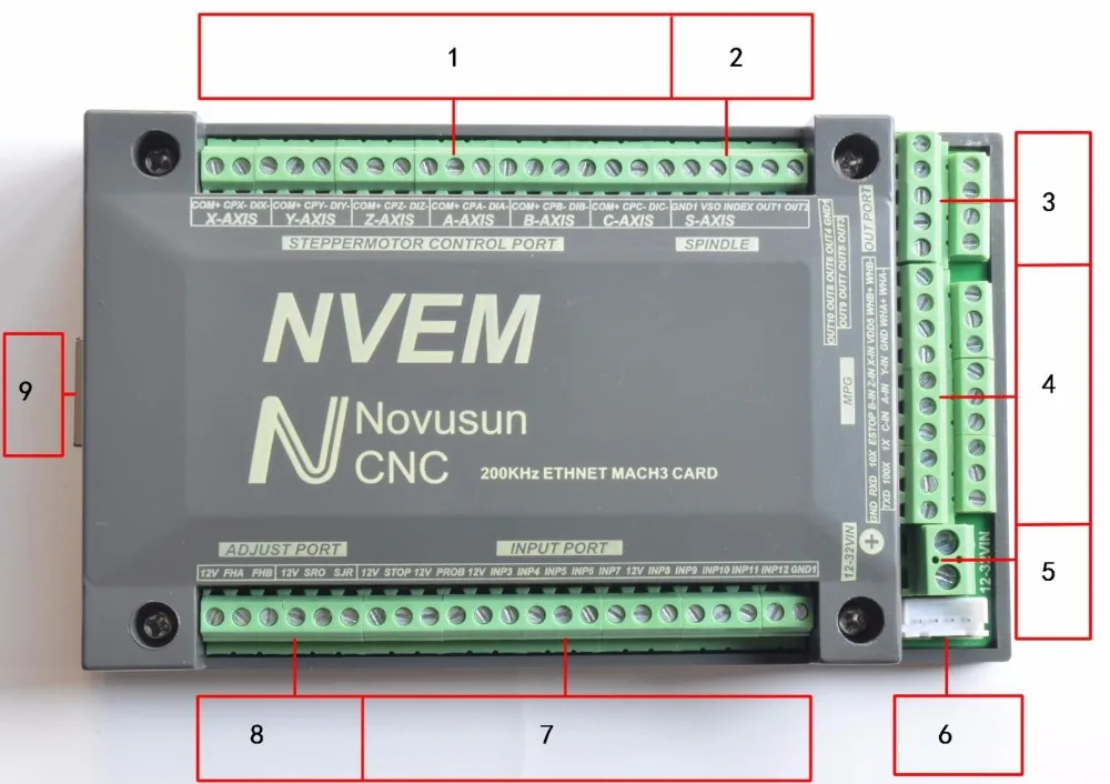
Product wiring section and interface summary
As the figure showed,the connection of the controller includes power supply interface,Ethernet connection interface,MPGinterface,Stepper/Servo control output interface,spindle control output interface, Estop and limited switch and tool setting input interface and so on. Now we descript them in details as below.
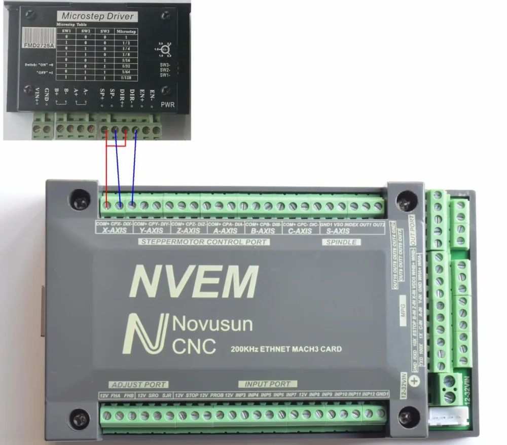
2.1) Stepper motor control interface
No.1 terminal block is 6 axis stepper driver control output interface, from left to right,there are X,Y,Z,A,,B,C 6 axis output, it’s common anode,the cable connection for each axis is COM+/CP-/DIR-, COM is common+ ,CP is Pulse-, DIR is direction-.Connection showed as Figure 2-3.COM+ connect with the SP+ and DIR+.
Pin mark Axis Definition COM+ Commom+ common anode +5V CPX- X axis Pulse output- for X axis DIX- X axis Directrion output- for X axis CPY- Y axis Pulse output- for Y axis DIY- Y axis Directrion output- for Y axis CPZ- Z axis Pulse output- for Z axis DIZ- Z axis Directrion output- for Z axis CPA- A axis Pulse output- for A axis DIA- A axis Directrion output- for A axis CPB- B axis Pulse output- for B axis DIB- B axis Directrion output- for B axis CPC- C axis Pulse output- for C axis DIC- C axis Directrion output- for C axis
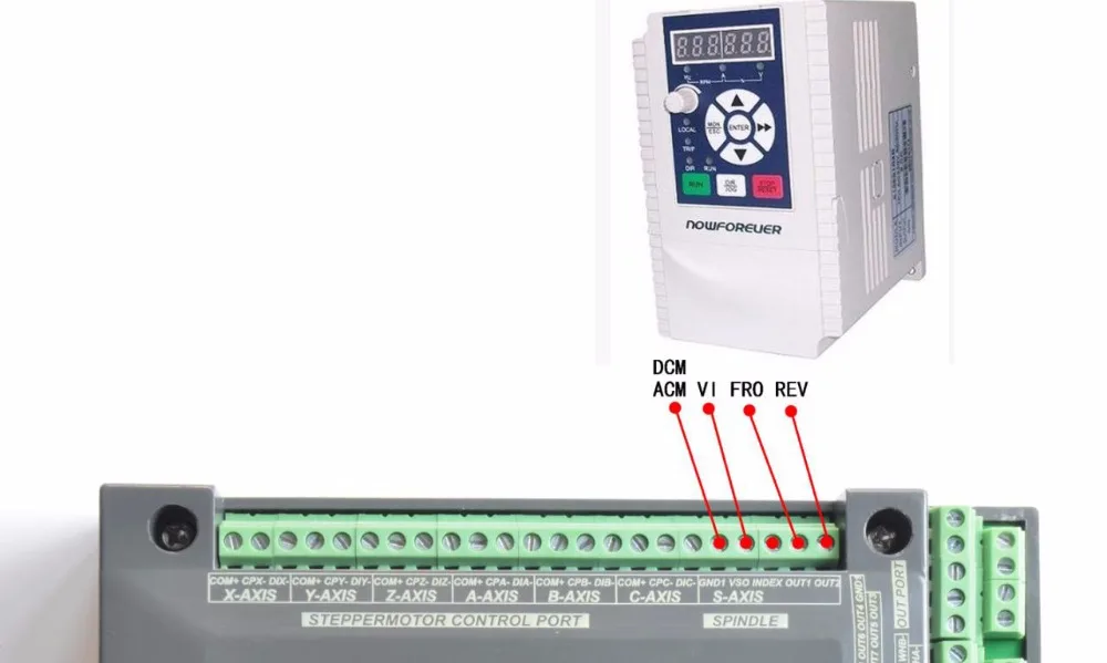
2.2) Spindle control output
We define the interface from left are: GND1(Output GND),VSO(0-10V adjustable speed output),INDEX(spindle speed feedback input),OUT1(common output port 1),OUT2(common output port 2),.
Take Nowforeuer inverter as the example. Spindle control output and the inverter connection showed as Figure 2-4.If ACM and DCM are closed,only need to connect one port.
If need the Mach 3 to show the real in time spindle speed,just fix one hall device,every revolution send one pulse between INDEX and GND1,pulse voltage is 5V-10V.
4 Axis Ethernet MACH3 Motion Control Card NVEM
NVEM V2 is the 3-6 axis motion controller we spend 4 years to design.
NVEM V2 support Mach3 software and standard MPG,through Ethernet to communicate with computer,just use the Twine to connect directly or transfer with router. NVEM V2 motion controller adopts the ARM design framework. The ARM design includes communication, codeanalytic,underlying algorithm and pulse gerneration.Rational design,reliablecontrol, convenient operation. This manual introduces operation,connection and usage schedule of our professional motion controller for engraving machine.Through a lot of the drawing the users can learn quickly how to use this motion controller.
1.2 Performance parameter
Features: 1) Can control up to 3/4/5/6 stepper motor at the same time. 2) Support Motor: Servo motor, Stepper motor. 3) With 12 channel programmable input port. 4) With 10 channel programmable output port. 5) 1 channel standard MPG interface 6) PWM output control 7) Ethernet interface, support MACH3 software 8) DC electrical isolation 9) Optocoupler isolation 10) Up to 200KHz stepper motor control pulse output Specification: 1) Support Ethernet; 2) 12 ports photoelectric isolated input interface for ordinary digital data; 3) 10 ports photoelectric isolated output interface for ordinary digital data; 4) 1 port 0-10V spindle speed analog output interface(can change to PWM output); 5) Can support 3-6 axis stepper systems,200KHz pulse output for every axis; 6) ARM motion control chip; 7) Main device is 12V-32VDC power supply input,current should higher than 0.5A; 8) Compatible with MPG input,support the digital display MPG from our company.
NVEM V2 is the 3-6 axis motion controller we spend 4 years to design.
Product wiring section and interface summary
As the figure showed,the connection of the controller includes power supply interface,Ethernet connection interface,MPGinterface,Stepper/Servo control output interface,spindle control output interface, Estop and limited switch and tool setting input interface and so on. Now we descript them in details as below.
2.1) Stepper motor control interface
No.1 terminal block is 6 axis stepper driver control output interface, from left to right,there are X,Y,Z,A,,B,C 6 axis output, it’s common anode,the cable connection for each axis is COM+/CP-/DIR-, COM is common+ ,CP is Pulse-, DIR is direction-.Connection showed as Figure 2-3.COM+ connect with the SP+ and DIR+.
| Pin mark | Axis | Definition | ||
| COM+ | Commom+ | common anode +5V | ||
| CPX- | X axis | Pulse output- for X axis | ||
| DIX- | X axis | Directrion output- for X axis | ||
| CPY- | Y axis | Pulse output- for Y axis | ||
| DIY- | Y axis | Directrion output- for Y axis | ||
| CPZ- | Z axis | Pulse output- for Z axis | ||
| DIZ- | Z axis | Directrion output- for Z axis | ||
| CPA- | A axis | Pulse output- for A axis | ||
| DIA- | A axis | Directrion output- for A axis | ||
| CPB- | B axis | Pulse output- for B axis | ||
| DIB- | B axis | Directrion output- for B axis | ||
| CPC- | C axis | Pulse output- for C axis | ||
| DIC- | C axis | Directrion output- for C axis | ||
| |
2.2) Spindle control output
We define the interface from left are: GND1(Output GND),VSO(0-10V adjustable speed output),INDEX(spindle speed feedback input),OUT1(common output port 1),OUT2(common output port 2),.
Take Nowforeuer inverter as the example. Spindle control output and the inverter connection showed as Figure 2-4.If ACM and DCM are closed,only need to connect one port.
If need the Mach 3 to show the real in time spindle speed,just fix one hall device,every revolution send one pulse between INDEX and GND1,pulse voltage is 5V-10V.
Feedback:
We maintain hightest buyer ratings
> Positive Feedback will be much appreciated from you.
> Any dissatisfaction,please contact us immediately!
> Please do not leave neutral or negative feedback before we help you out.
Returns:
> Defect: We will fully refund or send you a new replacement,please contact and return within 30 days.
> Dissatisfaction: Please contact within 3 days, we will fully refund, after got your returned goods.
> Missing parts/Q'ty: Please contact us immediately,for a new package arranged,or a partial refund issued.
Contact us:
> If have any question, Please contact us by ebay message before leaving neutral, negative feedback or open any dispute, we will reply within 24hours, ensure that help you solve the problem, make you satisfied.
