LED, Green/Yellow Bi-Color, 3-wire, LiteOn, T- 1 3/4 PN: LTL-30EDJ (Quantity 2) |

|
View of two of these LEDs, left LED with its |
|
Part Number: LTL-30EDJ Colors: Yellow and Green Leads: Three Common (center) Lead: Cathodes Lead spacing: .1" (2.54 mm) Package: T - 1 3/4 Max. reverse Voltage: 5 volts |
|
Physical Characteristics |
|
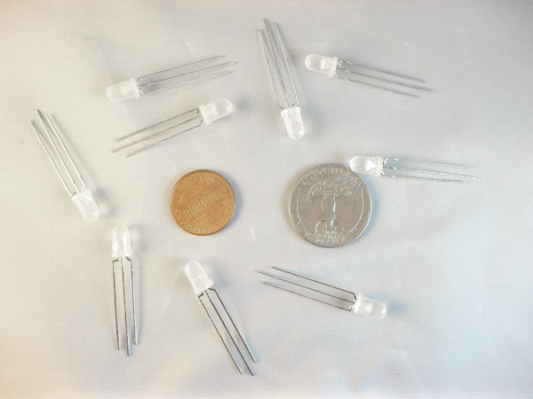
As you can see above and below, these LEDs have the standard T-1 3/4 packages. Their leads are long enough that, if you want to, you can bring them up off your circuit board, bend them into a right angle, and stick them through a .2" hole in the front panel. Their lead spacing is the standard .1" from one lead to the next. The lead lengths are slightly staggered so that you can tell them apart ― with the yellow lead longer than the green. Trouble is, they made it only very slightly longer; if the leads are slightly bent, it's hard to tell which is the longer outer lead. Getting this part in backwards would be easy to do. In addition, as you can see in the top right and the lower left above, they put a small notch in the 1mm flange (ring) around the part. But, it's such a very small notch that I, at least, had to use a magnifying glass in order to be sure it was there at all. I'm sure you can't see it at all in the photo below. It's just above the yellow lead. I think it would have been better to make the yellow lead the longest one, the middle lead next, and then the short green lead. That way, when looking at the lead lengths, you could more easily orient the part correctly. |

|
The question I had was "What does it look like if you turn both halves of the LED on at the same time?" So I tried it. I suppose I should have guessed the answer: It looked kind of yellow and kind of green, but not really either. Also, I should add that for the yellow/green photo at the top of this description (the photo with the red border) I drove the LED at about the standard LED current of 20 ma. And, as you can see from the specs, the maximum reverse (off) voltage is 5 volts, so be sure not to exceed that. |

|
I don't wish to insult most of you who might consider buying this part and probably know more about using LEDs than I do, but there will probably be a few who are using this part for the first time. This is for these first time users: Say you're using Circuit model A below (Circuit madel B makes no sense, don't use it), in a circuit that has a +5 volt power supply. You connect the output of an IC which is capable of driving 20ma to the left side of the top resistor. The right side of the top resistor is connected to the yellow LED. The middle LED lead, the one on the right, is connected to ground (0volts). And, you connect a similar IC, IC2 to the left side of the lower resistor. The right side of the lower resistor you connect to the green LED. Whenever you want to turn the yellow LED color on, the voltage out of IC1 will be high, very near 5 volts. This will turn the yellow LED on, and the current will be about 20ma. The voltage across a lighted LED will be naturally go to about 2.2 volts (see the diagram 'forward voltage versus forward current') above. Therefore, the voltage across the resistor will be 5v - 2.2v = 2.8v. The resistor, then, must be about 2.8v/.02a = 140Ω. Select a common resistor size, say 150Ω, and you're all set. That takes care of the yellow side. The power is very low (it takes very little power to drive an LED), so even a small physical sized resistor will do. The arithmetic is the same for the green side of the LED, so a 150Ω resistor will work for that side too. [It's important to note though, that if the circuit voltage is more than 5 volts, the arithmetic is slightly different. Also, many ICs are not capable of directly driving even the small amount of current called for, 20ma. You may have to select an IC specifically for that capability. That's why transistors are often used to drive LEDs ― they're smaller sized and usually cheaper than ICs.] You'll generally want avoid any situation in which both the yellow and green sides are ever allowed to be on at the same time. I don't think it would would hurt anything, but it's just not good ergonomics to design something that causes your user to ask himself, "Is that yellow or green, I just can't tell." Now, in the circuit we've been talking about, if IC1 is on and IC2 is off, the LED will be turned on and yellow. If IC2 is on and IC1 is off, the LED will be turned on and green. If they're both off, the LED is off. But, if they're both on, that's the problem. The best way to avoid this problem is this: You use inverting ICs, and you not only tie IC1's output to the yellow LED input, you also use it as the only input to IC2. In this way, IC1's output is also the signal driving IC2, and the LED will always be either yellow or green, dependent upon the input to IC1. Of course, as is common in electronics, there are lots of ways to do anything, and so are there are lots ways to use parts such as these bi-color LEDs. One use is to visually indicate which position a SPDT switch is in. Another would be to be make a custom light by using a lot of these LEDs clustered on a circuit board ― even a prototype board. You could make it light up either yellow or green, but with half the LEDs and in half the space it would normally take, and with all the light seemingly coming from exactly the same place. I'm sure there are lots of other ideas that you'll come up with. |

|
I have other miscellaneous items which may or may not fit into my store's normal categories. If you'd like to see them, just click the green link below. |
|
Click here to see my Other Items Click here to visit my store (list view) Click here to visit my store (gallery view) Click here to save me as a seller |