|
This item will be shipped from Germany local warehouse by DHL or GLS to European Union Customers. For European Union Customers, It will be more faster to receive this parcel and easy to avoid import tax. Only EU country ,shipping from Our germany warehouse,other country shipping from china |
|
|


2. Stepper motor driver DM542A:

Introduction:
DM542A is a type of two-phase hybrid stepping motor driver, The drive voltage of which is from 18VDC to 50VDC. It is designed for use with 2-phase hybrid stepper motor of all kinds with 42mm to 86mm outside diameter and less than 4.0A phase current. This circuit that it adopts is similar to the circuit of servo control which enables the motor run smoothly almost without noise and vibration. Hording torque when DM542A run under high speed is also significantly higher than the other two-phase driver, what’s more, the positioning accuracy is also higher. It is widely used in middle and big size numerical control devices such as curving machine, CNC machine, and computer embroider machine, packing machines and so on.
Features:
· High performance, low price
· Average current control, 2-phase sinusoidal output current drive
· Supply voltage from 18VDC to 50VDC
· Opto-isolated signal I/O
· Overvoltage, under voltage, overcorrect, phase short circuit protection
· 15 channels subdivision and automatic idle-current reduction
· 8 channels output phase current setting
· Offline command input terminal
· Motor torque is related with speed, but not related with step/revolution
· High start speed
· High hording torque under high speed
| Pin Function | Details |
| PUL +,PUL- |
Pulse signal, PUL+ is the positive end of pulses input pin
PUL- is the negative end of pulse input pin
|
| DIR+,DIR- |
DIR signal: DIR+ is the positive end of direction input pin
DIR- is the negative end of direction input pin
|
|
ENBL+
|
Enable signal: ENBL+ is the positive end of direction input pin. This signal is used for enabling/disabling the driver. High level for enabling the driver and low level for disabling the driver. |
| ENBL- | ENBL- is the negative end of direction input pin. Usually left unconnected (enabled) |
Fig 1. Input port circuit (Yang connection)
PC open connector output
Fig. 2 Input port circuit ( Yin connection)
PC PNP output
Note: When VCC=5V, R=0
When VCC=12V, R=1K, >1/8W
When VCC=24V, R=2K,>1/8W
R must connect in the control signal part.
3. Function choice ( Using DIP pins to achieve this function)
1) Micro step resolution is set by SW 5,6,7,8 of the DIP switch as shown in the following table:
|
SW5 |
OFF |
ON |
OFF |
ON |
OFF |
ON |
OFF |
ON |
OFF |
ON |
OFF |
ON |
OFF |
ON |
OFF |
|
SW6 |
ON |
OFF |
OFF |
ON |
ON |
OFF |
OFF |
ON |
ON |
OFF |
OFF |
ON |
ON |
OFF |
OFF |
|
SW7 |
ON |
ON |
ON |
OFF |
OFF |
OFF |
OFF |
ON |
ON |
ON |
ON |
OFF |
OFF |
OFF |
OFF |
|
SW8 |
ON |
ON |
ON |
ON |
ON |
ON |
ON |
OFF |
OFF |
OFF |
OFF |
OFF |
OFF |
OFF |
OFF |
|
PULSE/REV |
400 |
800 |
1600 |
3200 |
6400 |
12800 |
25600 |
1000 |
2000 |
4000 |
5000 |
8000 |
10000 |
20000 |
25000 |
2) Standstill current setting
SW4 is used for this purpose. OFF meaning that the standstill current is set to be half of the selected dynamic current and ON meaning that standstill is set to be the same as the selected dynamic current.
3) Output current setting:
The first three bits (SW 1, 2, 3) of the DIP switch are used to set the dynamic current. Select a setting
Closest to your motor’s required current
|
Output current (A) |
||||
|
SW1 |
SW2 |
SW3 |
PEAK |
RMS |
|
ON |
ON |
ON |
1.00 |
0.71 |
|
OFF |
ON |
ON |
1.46 |
1.04 |
|
ON |
OFF |
ON |
1.91 |
1.36 |
|
OFF |
OFF |
ON |
2.37 |
1.69 |
|
ON |
ON |
OFF |
2.84 |
2.03 |
|
OFF |
ON |
OFF |
3.31 |
2.36 |
|
ON |
OFF |
OFF |
3.76 |
2.69 |
|
OFF |
OFF |
OFF |
4.20 |
3.00 |
4) Semi-flow function:
Semi-flow function is that there is not step pulse after 500 ms, the driver output current automatically reduced to 70% of rated output current, which is used to prevent motor heat.
4. Power connections
(1)+V、GND:Power Supply.
+V: Power supply, 16~50 VDC, Including voltage fluctuation and EMF voltage. The max current is 5A.
(2) A+ A- B+ B-:Connecting 2 phase stepper motors.
The driver & 2-phase hybrid stepping motor use four-wire connection, the motor can be connected in parallel & series bipolar. As for bipolar connection, it is higher performance with high-speed, but the current of driver is larger (it is 1.73 times more than the motor’s winding current).
Connecting in series, the driver’s current is equal to the motor winding one.
5. Fixing
There should be 20mm of space, it can’t be placed next to other heating devices, to avoid dust, oil mist, corrosive gas, humidity and strong vibration places.
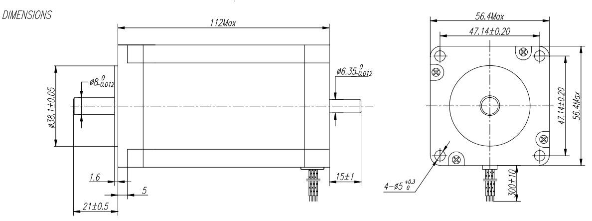
(Unit=mm)
6. Troubleshooting
1, the status on light’s indication
RUN: green, normal work light.
ERR: red, failure light, the motor with phase short-circuit, overvoltage and under-voltage protection.
2 Troubles
|
Alarm indicator
|
Causes |
Measures |
|
LED off turn |
Wrong connection for power |
Check wiring of power |
|
Low-voltages for power |
Enlarge voltage of power |
|
|
Motor doesn’t run, without holding torque |
Wrong connection of stepper motor |
Correct its wiring |
|
RESET signal is effective when offline |
Make RESET ineffective |
|
|
Motor doesn’t run, butmaintains holding torque |
Without input pulse signal |
Adjust PMW & signal level |
|
Motor runs wrong direction |
Wrong wires’ connection |
Change connection for any of 2 wires |
|
Wrong input direction signal |
Change direction setting |
|
|
Motor’s holding torque is too small |
Too small relative to current setting |
Correct rated current setting |
|
Acceleration is too fast |
Reduce the acceleration |
|
|
Motor stalls |
Rule out mechanical failure |
|
|
Driver does not match with the motor |
Change a suitable driver |
7. Driver Wiring
A complete stepper motor control system should contain stepper drives, DC power supply and controller (pulse source).
3.Power Supply
The power is 350Watts, and the output voltage is 36VDC.
4,Breakout board
Description:
• Built in DB25 male connector.
• DB25 Output Pin:P1,P2,P3,P4,P5,P6,P7,P8,P9,P14,P16,P17.
• DB25 Input Pin: P10,P11,P12,P13,P15.
• DB25 GND Pin: P18-P25.
• Power supply: +5V DC.
• Built in C-class Optical-coupler.
• High quality with Surface-mount Tech
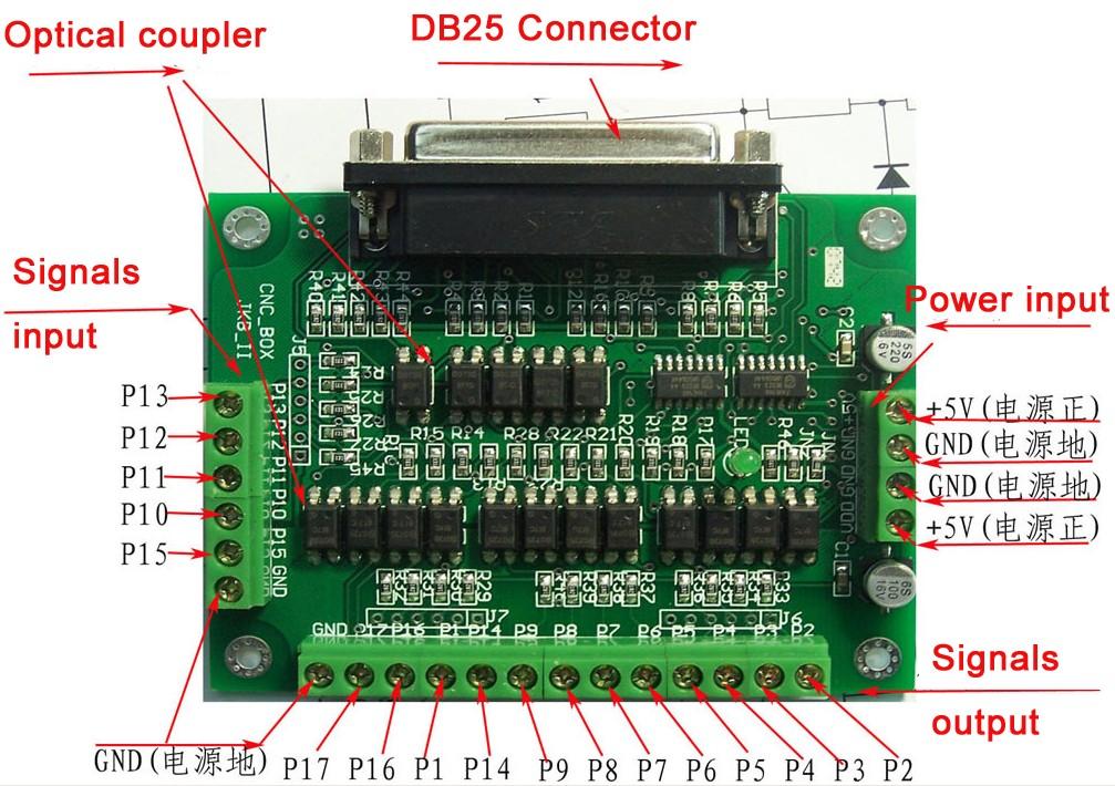
P2 P3 is set to X-axis for the X-axis pulse
P4 P5 is set to Y-axis, Y axis pulse
P6 P7 is set to Z-axis Z-axis pulse
The other can be set to A B C axis
A-axis pulse P8 P9 is set as the A axis
P14 is set to B-axis B-axis pulse P1
P16 P17 is set to C-axis, C axis pulse
Can also be set to the spindle control signal \ electrical permit
Input interface for the P10 P11 P12 P13 P15
Application:Our Stepper Motors are used on small to mid-sized CNC mills or milling machines, CNC lathes, Pick-n-place machines,Laser Engravers and Laser Cutters, Vinyl Sign Cutters, CNC Plasma Cutters, and CNC Foam Cutters. Carver machine ,Dispenser,Automazation,3D Printer,Stage lighting,instrument,laser equipment,scanner and so on.These motors have been used in precision telescope positioning systems and robots.