|
This item will be shipped from Germany local warehouse by DHL or GLS to European Union Customers. For European Union Customers, It will be more faster to receive this parcel and easy to avoid import tax. |
||||||||||||||||||||||||||||||||||||||||||||||||||||||||||||||||||||||||||||||||||||||||||||||||||||||||||||||||||||||||||||||||||||||||||||||||||||||||||||||||||||||||||||||||||||||||||||||||||||||
1. Stepper motorFeatures: 1.High torque, More smooth movement 2.High efficiency, energy-saving, low noise, low vibration, high start torque, low start current and reliable performance. 3.We offfer mach 3 software by free,if you want please download on our website. After you payment,I will send electronic manual to your e-mail,if you not receive,you tell me your e-mail,I iwll send to you. 3 pcs Nema 34 stepper motor 1600 oz.in bipolar with single Shaft
3pcs Stepper motor driver, DM860A, peak 7.8A ,256 Micsteps,replacing M860
3 pcs Power Supply 350W-60VDC
1 pc Breakout Board & 1 pc parallel cable
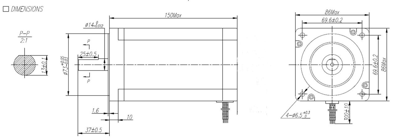
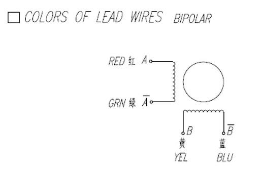
Technical Specifications Part No.: 34HS5435C-37B2 Frame Size: NEMA34 Phase: 2 Phase Step Angle: 1.8 degree Current: 3.5A Rated Voltage: 5.6V Resistance: 1.6 Ohm/phase Inductance: 22mH/phase Holding torque: 1600oz-in (10.5N.m) Detent torque: 24.5N.cm Rotor inertia: 3600g.cm² Number of wire leads: 4 (Red A+ ,Green A- ,Yellow B+ ,Blue B-) Weight: 5kg Length: 151mm Front shaft length 37mm The diameter for motor shaft is 14mm Matched drive:DM860A Shaft:Single Shaft
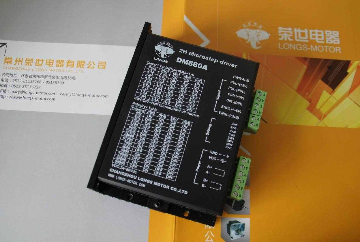
2. Stepper motor driver DM860A:
Introduction: DM860A is a type of two-phase hybrid stepping motor driver, The drive voltage of which is from 24VDC to 80VDC. It is designed for use with 2-phase hybrid stepper motor of all kinds with 57mm to 110mm outside diameter and less than 8.0A phase current. This circuit that it adopts is similar to the circuit of servo control which enables the motor run smoothly almost without noise and vibration. Hording torque when DM860A run under high speed is also significantly higher than the other two-phase driver, what’s more, the positioning accuracy is also higher. It is widely used in middle and big size numerical control devices such as curving machine, CNC machine, and computer embroider machine, packing machines and so on. Features: l High performance, low price l Average current control, 2-phase sinusoidal output current drive l Supply voltage from 24VDC to 80VDC l Opto-isolated signal I/O l Overvoltage, under voltage, overcorrect, phase short circuit protection l 14 channels subdivision and automatic idle-current reduction l 8 channels output phase current setting l Offline command input terminal l Motor torque is related with speed, but not related with step/revolution l High start speed l High hording torque under high speed Electrical specification:
Pins assignments and description: 1) Connector Pins Configurations
2) Pins wiring diagram: PC’s control signals can be active in high and low electrical level. When the high electrical level is active, all control negative signals will be connected together to GND. When low electrical level is active, all control positive signals will be connected together to public port. Now give two examples( Open collector &PNP), please check them: Fig 1. Input port circuit (Yang connection) PC open connector output Fig. 2 Input port circuit ( Yin connection) PC PNP output Note: When VCC=5V, R=0 When VCC=12V, R=1K, >1/8W When VCC=24V, R=2K,>1/8W R must connect in the control signal part . 3.Function choice ( Using DIP pins to achieve this function) 1) Micro step resolution is set by SW 5,6,7,8 of the DIP switch as shown in the following table:
2) Standstill current setting SW4 is used for this purpose. OFF meaning that the standstill current is set to be half of the selected dynamic current and ON meaning that standstill is set to be the same as the selected dynamic current. 3) Output current setting: The first three bits (SW 1, 2, 3)of the DIP switch are used to set the dynamic current. Select a setting Closest to your motor’s required current
4) Semi-flow function: Semi-flow function is that there is not step pulse after200 ms, the driver output current automatically reduced to 40% of rated output current, which is used to prevent motor heat. 4. Pins of motor & power:
5. Mechanical Specification: To have 20mm of space around ,cannot be placed next to other heating devices. What’s more, avoid dust, oil mist, corrosive gas, heavy humidity and high vibration. (Unit=mm) 6. Adjustment of troubleshooting 1) , the status on light’s indication PWR: green, normal work light. ALM: red, failure light, the motor with phase short-circuit, overvoltage and under-voltage protection. 2) Troubles
7. Driver wiring A complete stepper motor control system should contain stepper drives, DC power supply and controller (pulse source). 3.Power Supply 350W-60V 4. Breakout Board & 1 pc parallal cable General in the software P2 P3 is set to X-axis for the X-axis pulse P4 P5 is set to Y-axis, Y axis pulse P6 P7 is set to Z-axis Z-axis pulse The other can be set to A B C axis A-axis pulse P8 P9 is set as the A axis P14 is set to B-axis B-axis pulse P1 P16 P17 is set to C-axis, C axis pulse Can also be set to the spindle control signal \ electrical permit Input interface for the P10 P11 P12 P13 P15
Description: • Built in DB25 male connector. • DB25 Output Pin:P1,P2,P3,P4,P5,P6,P7,P8,P9,P14,P16,P17. • DB25 Input Pin: P10,P11,P12,P13,P15. • DB25 GND Pin: P18-P25. • Power supply: +5V DC. • Built in C-class Optical-coupler. • High quality with Surface-mount Tech.
Application:Our Stepper Motors are used on small to mid-sized CNC mills or milling machines, CNC lathes, Pick-n-place machines,Laser Engravers and Laser Cutters, Vinyl Sign Cutters, CNC Plasma Cutters, and CNC Foam Cutters. Carver machine ,Dispenser,Automazation,3D Printer,Stage lighting,instrument,laser equipment,scanner and so on.These motors have been used in precision telescope positioning systems and robots.
|
||||||||||||||||||||||||||||||||||||||||||||||||||||||||||||||||||||||||||||||||||||||||||||||||||||||||||||||||||||||||||||||||||||||||||||||||||||||||||||||||||||||||||||||||||||||||||||||||||||||