| Model No. | TD003 |
| Function discription | Encoder Transmitter modules |
| Operating voltage | 5V ~ 12V DC (recommand in 12V , best performance ) |
| Static current | max≤10mA(12V), min≤4mA(5V) |
| Operating frequency | 433MHz |
| modulation Mode | ASK/OOK |
| SAW Frequency stability | ±150kHz(max) |
| RC Resistance | 4.7M |
| Transmitter Power | 50mW(315MHz, 12V) |
| Data rate | ≤10Kbps |
| Antenns length | 24 cm (315 MHz), |
| Dimension | 40mm*20mm*10mm |
| Encodeing format | SC2262 fixing code (same as PT2262 PT2264) ,Work with PT2272 PT2264 decoder IC |
| Transmitter distance | 500-100M (open area) |
Description:
Model No.: RF11A04 OR CE-RF11A-045V
1. Features:
Operating voltage: DC 3-5V
Operating current: less 11mA (DC 5V)
Working priceple: super heterodyne
modulation Mode: OOK / ASK
Operating Frequency : 433.92MHZ
Receiving sensitivity: -108dBm
Output level: 5V TTL level, low standby, the maximum current 20MA (to add a current-limiting resistor)
Decode: learning code, adapted EV1527 / PT2262 and a compatible remote control, you can store up to eight remote control
Working modes: Non-locking (Momentary ), self-locking (Toggle), Inter-locking; 0.1-500000 seconds adjustable delay time
Size: 30x12.1x12.5mm
Weight: 4 grams or less
2. Pin Description
G: GND pin, DC 3-5V power supply negative
V: VCC pin, DC 3-5V positive power supply
D0: channel 1 output, active high
D1: channel 2 output, active high
D2: Channel 3 output, active high
D3: Channel 4 output, active high
VT: channel output valid signal, the microcontroller can be used as an interrupt signal
3. the working mode

You can select different modes of operation with"M4 M3 M2 M1 M0" pad in the delay mode to adjust the delay time through an adjustable resistor.
In delay mode, the rotary variable resistor can adjust the delay time. Increase the time counterclockwise rotation, and clockwise rotation to shorten the time. Adjustable resistor is a precision resistor, adjust the time with a Phillips screwdriver to gently rotate (do not use excessive force)
Working Mode Description:
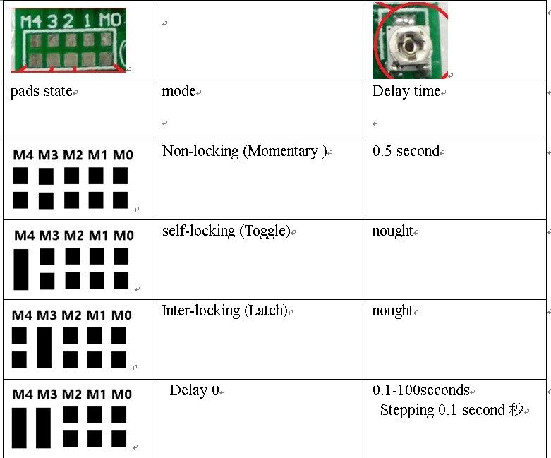

Non-locking: Press the remote control button, the IO port outputs high. Release the remote control button, IO port outputs low.
Self-locking: Press the remote control button, the IO port outputs high. Press the remote control button again, IO port outputs low.
Interlock: Press the remote control button D0, D0 IO port outputs high, other IO ports outputs low; remote control button is pressed D1, D1 IO port outputs high, other IO ports output low and so on.
Delay: Under Delay mode, there is a delay 0/1/2/3/4 five sub-patterns, by adjusting the variable resistor IO port high duration
4, the adapter remote control (learning remote control)
In normal operation mode, LED (D1) will be lit, when receiving a valid remote control (EV1527 / PT2262) key value, LED will flash.
Clean code: hold the button to press.LED offs, keep pressing about 8 seconds until LED lights. At that time, clean code completion (Note: After the implementation of clean code, previous remote controls do not exist.
Adaptation (learning):
Step 1 (into the learning mode):trigger the key button, LED offs;
Step 2 (adapter channel 1): press the first button of remote control and then, LED offs after flashes for four times. This time means that it had learned the value of the first button
Step 3 (Adaptation Channel 2): Press the second remote control, LED offs after flashes 4 times, This time means that it had learned the value of the second button
Step 4 (adapter Channel 3): Then press the remote's third button, LED offs after flashes 4 times, This time means that it had learned the value of the third button
Step 5 (Adaptation Channel 4): Then press the remote control's fourth button, LED lights after flashes 4 times, This time means that it had learned the value of the fourth button.
NOTE: The process must be completed within 15 seconds
5. Wiring Diagram :
Control LED indicator: see "RF11A04_LED demo"
Control 12V Relay: See "RF11A04_4Relay demo"
Wiring
Screws were countersunk from the back of the acrylic. A wire was attached to each screw and then to a digital pin on the Arduino. When the wiper with the 5v wire touches the screw it pulls the digital pin high on the Arduino. Please see the schematic for further details.
Step 4: Program
Disclaimer: I am not a programmer and therefore the below code may not be the most efficient. Feel free to improve the code for your own uses if you see any errors or problems. It works for me so I hope it works for you.
// turn CW to lock and CCW to unlock
//1700 CCW; 1500 Stop; 1300 CW
//written by Chris Rybitski
#include
Servo deadbolt; // create servo
const int CWLimit = 6; // Limit Switch on 6 Unlock
const int CCWLimit = 7; // Limit Switch on 7 Lock
const int Redbtn = 12; //red push button
const int Blackbtn = 8; //black push button
const int GreenLED = 10; // Green LED
const int RedLED = 11; //Red LED
const int Ch1 = 5; //rf channel 1
const int Ch2 = 4; //rf channel 2
const int Buzz = 9; //buzzer
int Unlock = 0;
int Lock = 0;
int timer = 0;
boolean UnLcomplete = false;
boolean Lcomplete = false;
void setup()
{
Serial.begin(9600);
deadbolt.attach(3); // attaches the servo
pinMode(GreenLED, OUTPUT);
pinMode(RedLED, OUTPUT);
pinMode(Buzz,OUTPUT);
pinMode(CWLimit, INPUT);
pinMode(CCWLimit, INPUT);
pinMode(Redbtn, INPUT);
pinMode(Blackbtn, INPUT);
pinMode(Ch1, INPUT);
pinMode(Ch2, INPUT);
//set LED's and Buzzer to be off by default
digitalWrite(GreenLED, HIGH);
digitalWrite(RedLED, HIGH);
digitalWrite(Buzz, HIGH);
}
void loop()
{
if (digitalRead(Ch1) == HIGH || digitalRead(Redbtn) == LOW){ //If remote or button is pressed
if(UnLcomplete == false){ //dont run unlock if door is already unlocked
Serial.println("UnLock");
Unlock = 1;}}
if (digitalRead(Ch2) == HIGH || digitalRead(Blackbtn) == LOW){ //If remote or button is pressed
if(Lcomplete == false){ //dont run lock if door is already locked
Serial.println("Lock");
Lock = 1;}}
//---------------UNLOCK-------------------------
if (Unlock == 1){
timer = 0;
while (digitalRead(CWLimit) == LOW){
if (timer > 1500){
digitalWrite(Buzz, LOW);
delay(500);
digitalWrite(Buzz, HIGH);
}
else{
deadbolt.write(1700);
timer++;
delay(1);
}}
deadbolt.write(1500); //servo stop
digitalWrite(RedLED, LOW);
digitalWrite(GreenLED, HIGH);
UnLcomplete = true; //unlock complete
Lcomplete = false; //reset Lock boolean
digitalWrite(Buzz, LOW);
delay(100);
digitalWrite(Buzz, HIGH);
Unlock = 0; //reset
}
//--------------LOCK----------------------------
if (Lock == 1){
timer = 0;
while (digitalRead(CCWLimit) == LOW){
if (timer > 1500){
digitalWrite(Buzz, LOW);
delay(500);
digitalWrite(Buzz, HIGH);
}
else{
deadbolt.write(1300);
timer++;
delay(1);
}}
deadbolt.write(1500);
digitalWrite(GreenLED, LOW);
digitalWrite(RedLED, HIGH);
Lcomplete = true; //lock complete
UnLcomplete = false; //reset Lock boolean
digitalWrite(Buzz, LOW);
delay(100);
digitalWrite(Buzz, HIGH);
delay(50);
digitalWrite(Buzz, LOW);
delay(100);
digitalWrite(Buzz, HIGH);
Lock = 0; //reset
}
}